Project: Rte. 460 Connector Phase 1 Design-Build, Grassy Creek Bridge
Location: Breaks, Va.
Owner: Virginia DOT
Designers: Stantec (prime), Jansen Spaans Engineering Inc. (bridge)
Contractors: Bizzack Construction LLC (prime), CJ Mahan Construction Co. (bridge subcontractor), RS&H CS (owner’s rep/CEI)
Cost: $105 million
Start Date: Aug. 7, 2009
Completion Date: June 8, 2015
Locationally challenged
Remote Appalachian hills pose steep test for bridge builders
Height is a relative measure. You might think the tallest bridge in Virginia would tower over its surroundings. Actually, it is just level with the mountains around it.
The tough mountainous and unstable terrain influenced much of the bridge’s design and construction.
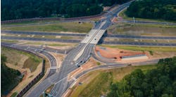
Grassy Creek Bridge has a vertical clearance of 250 ft above Grassy Creek in a project area with more than 400 ft of vertical elevation differential. The bridge consists of twin 1,700-ft-long cast-in-place segmental bridges, each with a deck width of 43 ft, carrying two lanes of traffic in both directions.
Constructed deep in the Appalachian Mountains, Grassy Creek Bridge is part of Phase 1 of the Rte. 460 Connector design-build project and No. 1 on Roads & Bridges’ 2013 Top 10 Bridges list. The bridge is currently about 55% complete.
The bridge is owned by the Virginia Department of Transportation, with RS&H CS contracted as the owner’s representative. The design-build team includes prime contractor Bizzack Construction, with bridge subcontractor CJ Mahan Construction Co., and prime designer Stantec, with bridge design subconsultant Jansen Spaans Engineering Inc.
The roadway and bridge approaches required a significant amount of both conventional and shape-charge blasting in order to prepare the site, which contains a variety of rock and soil conditions.
Rocky ground
The foundations for the bridge structures had to be quite diverse to compensate for the complex terrain. Because of the steep slopes on the site, the team had to evaluate slope stability as well as the usual factors in foundation design, such as eccentricity, overturning moment, sliding and bearing capacity.
“We not only have the terrain but we have coal seams in the area,” Mandy Cox, program manager for VDOT, told Roads & Bridges. “Subsurface investigation was a very strategic component during the design process.”
In one area of the bridge, the foundation was designed using micropiles, because of their advantages in locations with limited access, environmental sensitivity and close proximity to rock walls. The 36 micropiles on the project each has a design capacity of 182 tons and range in length from 40 to 80 ft deep.
The main piers of both the eastbound and the westbound bridges are reinforced concrete columns. The vertical reinforcing steel is 75 ksi surrounded by a low-permeability, 5,000-psi-compressive-strength concrete. The reinforcing steel is a corrosion-resistant, low-carbon/chromium steel, made by MMFX Steel Corp. of America, that also offers increased strength and should add significantly to the bridge’s durability.
Each pier on average uses 300,000 lb of reinforcing steel and 900 cu yd of concrete, cast in 20-ft sections.
The columns have a horizontal cross section that resembles an H. Because of the balanced-cantilever construction method of the superstructure, the columns have to be constructed to withstand a tremendous amount of bending moment.
“I understand originally they were going to be sort of a box-shaped pier column,” Mark Hirsch, program manager for RS&H, told Roads & Bridges, “and this was an innovation from the contractor to go with the H shape.”
The superstructure of the bridge is a 43-ft-wide, cast-in-place, variable-depth, segmental box. The depth of the segments varies from 30 ft at the piers to 12 ft at the mid-span closures. The variable-depth segments enable longer spans and give an aesthetically pleasing arch to the segments. The team chose to construct the superstructure by the cast-in-place, segmental, balanced-cantilever method because of the impracticality of hauling precast segments to the site through the surrounding mountains.
The team is constructing the superstructure using multiple sets of form travelers, which were designed and fabricated specifically for this project. Once construction of the piers has been completed, a pier table is constructed atop the piers. The form travelers are erected on either side of the pier table and surveyed into place. The next step is to set the reinforcing steel and post-tensioning ducts and tendons and then place the concrete. Once the concrete has reached a predetermined compressive strength, the post-tensioning tendons are stressed to a prescribed force in both the longitudinal and transverse directions. Each bridge is made up of 84 cast-in-place segments.
Mix-in-place construction
To supply the 16,000 cu yd of concrete needed to complete the project—and be sure it was delivered to the remote location in a timely manner—the team built an on-site concrete batch plant. The Johnson & Ross plant has the capability to produce 120 cu yd/hr of concrete. Since the plant became operational, the contractor has submitted—and the plant has produced—nearly 60 different custom concrete mix designs.
The bridge construction site is subject to intense weather conditions, including strong, gusting winds. To monitor the changing weather, the team installed a weather station and made the data remotely accessible.
The team also makes real-time pictures of the construction site available by way of a web camera. The camera is solar powered and operates on a cellular network. It aides the client in keeping up with the construction progress, as well as allows the general public to track the project.
The site is not just far away from any significant population center, it is 40 miles from the nearest town, so the project faced challenges attracting the skilled workforce it needed, procuring and delivering materials and maintaining communications with limited cell and Internet service.
For day-to-day project communications, the contractor instituted the use of two-way radios for all workers.
With limited options for housing the large workforce required to construct a project of this size, most of the management and labor force commute from the four neighboring states of West Virginia, Kentucky, Tennessee and Ohio. A project of this complexity also requires highly specialized talent and equipment for features such as the cast-in-place segmental construction process, blasting for site preparation, post-tensioning and grouting of steel tendons, etc. In order to attract the workers needed, the contractor is paying a premium, which is factored into the overall budget.
“This roadway truly is a bridge to economic development for this region,” Cox said. “The opportunities once this road is completed to be able to drive over into Kentucky in a timely manner is tremendous. They’ll be able to get to some of the larger communities in Kentucky and get a job.” R&B


