By: Kristin Higgins, P.E., and Tim Davis, P.E.
Vermont’s narrow scenic roadways and challenging landscapes make innovative bridge construction essential.
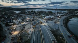
A recent project in Hartford involved two complete bridge replacements (bridges 43N and 43S) on I-91. These two bridges carry significant traffic over U.S. Rte. 5, which also is a high-volume roadway in Hartford. Both bridges were three-span structures with a pin-and-hanger type connection beyond the piers. These connections became problematic along the fascia beams and had required significant maintenance to address critical defects over the past five years. Because of the extensive maintenance repairs and a desire to remove bridges considered to be fracture critical from the Vermont interstate system, the bridges were programmed for replacement in 2012.
ABC vs. conventional construction
While the substructures for both bridges were in good shape, a future project to widen Rte. 5 and the desire for wider bridges on the interstate system resulted in a project scope recommending full replacement of both bridges. However, many constraints existed, which steered the scoping effort away from conventional construction using traditional traffic-control measures such as phasing or crossovers. First, the interchange for I-89/I-91 is located just south of the bridge at an exit to a major U.S. route. Furthermore, there are sharp curves, steep grades, a river crossing just north of the project and other unavoidable geographic constraints. Creative solutions for construction, while focusing on maintaining mobility with minimal traffic disruption, would be needed. As the project progressed through scoping, accelerated bridge construction (ABC) was determined to be the best solution for this site.
To ensure a fiscally efficient and constructible project, the Vermont Agency of Transportation (VTrans) opted to pursue the construction management / general contractor (CM/GC) contracting method to deliver and construct the Hartford project. Procuring a contractor with notable bridge experience for pre-construction and eventual construction services significantly reduced the risk of constructability issues and concerns associated with the traditional design-bid-build delivery method. Furthermore, it built confidence in the design team, given they had never designed such a complicated project.
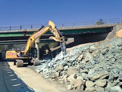
Bedrock excavation.
Designing for constructability
The VTrans project manager and designers collaborated together with the project manager and key personnel from PCL Civil Contractors to design and prepare a solid construction contract. From the beginning, means and methods for construction were considered. A prime example of the benefits of partnering occurred at the project kick-off meeting. The foundation type was critical, and while the 30% plans showed a mechanical stabilized earth wall with a shallow foundation abutment, PCL requested changing to a micropile foundation out of concern for the amount of excavation needed to install the wall reinforcement and bracing that would be required at the existing abutments to accommodate these long strips. The design team agreed to the concept and began exploring micropiles as the foundation for both bridges. Because of the low headroom for construction, it was essential to reach out to the subcontractor who would be installing them to determine an appropriate size of pile, given the overhead constraint. Once this information was available, the design could be completed and the number of piles necessary was certain. PCL was able to show financial benefits of the change in foundation type and prove the construction schedule would be able to accommodate this method of construction.
Getting underway
The Hartford Lateral Slide project was an ABC project on multiple fronts. The pre-construction services contract was executed in February 2014 with construction to be completed in October 2015, leaving 12 months for design and eight months for construction. Removing and reconstructing two bridges during this time frame was difficult; however, the use of the CM/GC delivery method made this schedule possible. General construction planning occurred alongside the design and costing exercises during pre-construction, allowing for only the final details to be sorted out during the construction phase.
With schedule as a driving factor, innovative construction techniques were evaluated. Precast deck forms were selected for use on the project. By using the precast forms, time required for the installation and removal of deck forms was eliminated from the schedule. The third ABC method was the lateral slide method, which will be discussed further later.
Foundations for the new structures were selected with constructability and schedule in mind. In order to meet the schedule and the project requirements, the foundations needed to be installed underneath the existing structure between the abutment and the existing pier. The easiest and most cost-effective way to install foundations was to excavate the slope to create access to the work area, and then install a micropile foundation. The bedrock layer is near the surface, making this a viable solution. The micropiles were then capped with a typical footing. The bedrock is near the surface at one of the four abutments, which allowed for a spread footing. A typical abutment wall with wing walls was constructed on top of the footing and backfilled to approximately 6 ft below the bottom of the existing steel beams. The abutment wall was cast within inches of those beams. Some portions of the wing were strategically left out to allow the new superstructure to slide through.
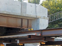
An Enerpac RR5020 jack system was used to slide elements into place.
Risk sequence
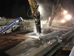
All of the glory is in the slide and all of the risk is in the demolition. Demolition of the existing bridges during the closure weekend was identified early in the process as the riskiest operation because of the unknowns and schedule impacts thereof. To mitigate this risk, one lane of the existing bridge was removed in advance of the closure weekend. This gave the team a chance to test out the demolition plan and troubleshoot any issues prior to fully shutting down I-91. This turned out to be a very smart mitigation technique, since the original demolition plan did not work.
I-91 closures were scheduled to occur prior to the seasonal traffic of the “leaf peepers.” The light traffic during this time of the year allowed I-91North to remain in a lane closure for an additional week while a new demolition plan was developed. The demolition of the existing structures was tricky because of the suspended midspan. As previously mentioned, the bearings of this span were in poor condition, which was the driving reason for the replacement of the structure in the first place. Tipping of the backspan beams was the second concern. The third concern was with the composite action of the suspended span. Shear studs existed only in the suspended span, and the girders could barely support the concrete deck load without the composite action. Finally, the backspan deck was intermittently tied to the beams with form hangers. These concerns led to a detailed sequence of demolition:
- Remove temporary barrier from bridge;
- Remove asphalt pavement/granite curb from bridge;
- Saw cut bridge deck, remove midspan deck panels;
- Remove approximately 40 ft of bridge deck near piers with percussive demolition;
- Slab crab removal of backspan deck slabs;
- Removal of suspended span girders;
- Removal of open joint and finger joint;
- Removal of backspan girders; and
- Removal of approach slab, abutment and piers.
There were multiple constraints and subsequences requiring detailed engineering at each step. Safety was the primary concern, and with large saw blades, torches, lead paint, large equipment and ever-present fall hazards, demolition during the closure was the most supervised activity. During each closure period, the bridge was successfully removed in approximately 18 hours.
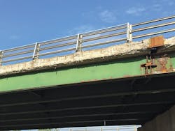
The existing facia beam hinge on the bridge, which was considered structurally deficient.
The slide
As previously mentioned, the lateral slide is the glory of the operation. During the bridge closures, the lateral slide was one of the fastest operations. It took approximately 4-5 hours to slide the bridge 60 ft. The success of a slide is determined in the upfront planning and layout. There are two fundamental rules that have to be followed for layout: The tracks have to be parallel and have relative matching elevations. Meeting these requirements is more difficult than it seems, because this has to accommodate mill tolerance, deflection and field tolerances. Bridge decks are not very flexible and minor deviations in elevations could lead to cracking.
A PTFE/stainless-steel sliding system was chosen for this project because of its ability to be adjusted easily in any plan dimension. The hydraulics were set up in such a way that the bridge could be steered as it was moved by simply starting one side ahead of the other. The disadvantage to this slide system was its sensitivity to the cleanliness and smoothness of the track. All dirt, debris, weld splatter, grease and oil was removed both from the PTFE pads and the stainless-steel tracks prior to the slide.
A common concern for lateral slide systems are the lateral forces that need to be restrained from pushing or pulling the bridge. This project used a system that maintained all of the forces internal to the system, resulting in internal axial loads instead of external horizontal loads. Accounting for this axial load in the support beam did not require any increase in section, reducing the cost in comparison to an externally braced system. The system consisted of a W section with a continuous stainless-steel surface welded to the top. A slide beam with PTFE pads positioned at girder locations slid along the top of the support beam. The 18-in. hydraulic jack pushed the slide beam while being restrained by tabs on the support beam. This system also kept all lateral forces out of the new superstructure. Impact factors were negligible since the superstructure moved at such a slow rate.
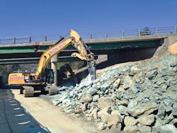
Cat H160E and 140E hammers being put to work demolishing the old deck.
In the road
If all of the risk is in the demolition, and all of the glory is in the slide, then all of the schedule is in the roadway construction. The roadway operation worked continuously throughout the closure period to maintain a measure of progress in line with the bridge work. Backfill was installed as much as possible prior to the closure period to reduce the workload during the weekend. Precast approach slabs were used to expedite roadway construction. The approach slab was constructed in two pieces at each end of the bridge to allow for crane erection. The slabs had blockouts placed in them that slid over dowel bars in the back wall. The closure between the slabs and the voids in the blockouts were filled during the closure period with a rapid-set concrete mix that achieved strength in less than two hours. After the fill and approach slabs were set, the roadway was paved, striped and opened to traffic.
Mutual investment by all stakeholders ultimately saw both bridges opened to traffic ahead of schedule. The Hartford Lateral Slide ABC project was forged in difficult circumstances, but brought to completion by a balance of managed risk and well-timed glory.
About The Author: Higgins is project manager for accelerated bridge programs at the Vermont Agency of Transportation. Davis is a district construction engineer with PCL Civil Contractors Inc.
