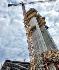
For years, expansion of the northern suburbs of the city of Belgrade has been hindered by the limited capacity of the three, existing bridges over the Sava river. In order to expand the capacity of the transportation network a fourth bridge was built. This impressive, cable-stayed beauty serves as a link between the district of New Belgrade on the northern bank and the city center on the southern bank.
With a structural height of 25 feet, width of 148 feet, and spanning 3,163 feet long, this bridge is the largest river crossing in the Balkan region. The project was complex, and not just because of the dimensions involved. In order to ensure uninterrupted shipping movements during construction, the main section spanning the Sava had to be erected in the river without temporary supports. In addition, construction had to be conducted on different sections simultaneously.
This was a truly international project, with teams from Serbia, Germany, Austria, Hungary, Slovenia, Switzerland, France, Great Britain, Denmark and China working on the project together under enormous time pressure. Only three years were scheduled as the construction period.
The operational engineering consultants responsible for the detailed planning and the agency that specialized in the planning of loadbearing structures worked out of Allplan Engineering, a 2D to 3D BIM software solution. This program, designed for interactive formwork and reinforcement planning, is particularly useful in building projects with complex geometries and reinforcement arrangements—perfectly suited for the Sava Bridge project.
Increasingly, 3D is becoming the necessary working method for elaborate and time-intensive engineering projects. In this case, the reinforcement planning of the complicated intersection area between the superstructure and the pylon was done in 3D, as was the planning of the anchoring for the 80 steel cables connecting the bridge decks of the main and retention areas to the pylon. Thanks to three-dimensional planning, the runs of the cables and their anchoring points could be precisely determined and visualized. Whenever and wherever sections and views were required, these could be derived at the desired location directly from the reinforcement model, allowing for precise, realistic plans and rapid implementation of design alterations.
The great strength of reinforcement planning in 3D lies in in the possibility of testing out variations of a design. A member of the engineering consulting firm explained, “When working with complicated geometrical conditions, in conjunction with high reinforcement levels, complex reinforcement patterns often arise. These can be produced and also optimized considerably faster using 3D planning together with the 3D animation. But even with simple reinforcement planning, working in 3D is still worthwhile, especially when amendments are made, as an adaptation in the 3D model no longer has to be carried out manually in all the sectional views. Allplan Engineering provides a significant advantage in such situations in comparison with 2D solutions.”
Since it’s opening in 2012, the Sava bridge has become an iconic symbol of the city, appearing in music videos, movies, commercials, and more.
Editor's Note: Scranton Gillette Communications and the SGC Infrastructure Group are not liable for the accuracy, efficacy and validity of the claims made in this piece. The views expressed in this content do not reflect the position of the Roads & Bridges' Editorial Team.

