Understanding AASHTO LRFD Bridge Design Specs for cast-in-place and post-installed anchoring systems
The AASHTO LRFD Bridge Design Specifications, 8th Edition, was published in November 2017. One change that occurred since the 7th Edition is the reorganization of Section 5, which is the design of bridge and ancillary structures constructed from reinforced concrete. The reorganization was headed up by the AASHTO T-10 Concrete Design Technical Committee of the Subcommittee on Bridges and Structures, with oversight from the Federal Highway Administration (FHWA), and invited industry liaisons from the concrete industry such as the Precast/Prestressed Concrete Institute (PCI) and the American Segmental Bridge Institute (ASBI). This reorganization is meant to harmonize, simplify and reduce the content while keeping it current. Some of the major revisions include:
- Further discussion on beam regions (B-Regions) and disturbed design regions (D-Regions);
- Reduction in the number of shear design procedures;
- Consolidation of prestressed and non-prestressed reinforcement details, plus seismic details, into three sections; and
- Reorganization of the sections to move common design topics to the front of the section.
The other major revision to Section 5 is the new article 13 which deals with the design of cast-in-place and post-installed anchors in concrete. Prior to the 8th Edition, the LRFD Bridge Design Specifications have not contained provisions on how to design anchor connections to concrete, regardless if this was a cast-in-place or post-installed anchor.
Cast-in-place and post-installed anchor systems have been used extensively in highway construction projects for many years for applications such as bridge girder connections, seismic retro-fit and strengthening, precast concrete member attachments, and attachments of light poles, signs, guard rails, and pedestrian fencing. Since there were no design provisions in the LRFD Bridge Design Specifications, engineers would use design provisions from other sources such as the Portland Cement Association (PCA) design handbook for cast-in-place anchors or from manufacturer’s product technical data in the case of post-installed anchors. And since 2002, some engineers working on road and bridge projects migrated over to ACI 318 Appendix D which provided design procedures for cast-in-place anchors and some post-installed anchor systems.
With the new reorganization of Section 5, there is now a direct reference to a design of anchor systems for road and bridge projects. The new Article 5.13 - Anchors, explains that the design, detailing, and installation of cast-in-place and post-installed anchors must follow the provisions of ACI 318-14 Chapter 17.
ACI 318-14 Chapter 17
ACI 318 Building Code Requirements for Structural Concrete have included provisions for designing cast-in and post-installed undercut and expansion anchors in concrete since the 2002 edition, and included post-installed adhesive anchors in 2011. From 2002 to 2011 the design provisions were contained in Appendix D - Anchoring to Concrete. In the 2014 edition of ACI 318, Appendix D became a full section and moved to Chapter 17 as part of the ACI 318 reorganization.
Article 5.13.1 and ACI 318 Chapter 17 are both intended for the following types of cast-in-place and post-installed anchor systems:
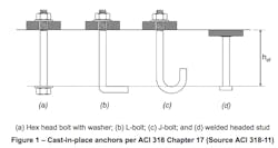
- Headed studs and headed bolts (see Figure 1);
- Hooked bolts (see Figure 1);
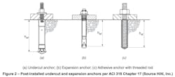
- Post-installed undercut and expansion anchors that meet the testing and assessment criteria ACI 355.2 (see Figure 2);
- Post-installed adhesive anchors that meet the testing and assessment criteria ACI 355.4 (see Figure 2); and
- Grouted anchors are excluded per Article 5.13.1 and are not addressed in ACI 318-14 Chapter 17.
Starting with the 2003 International Building Code (IBC), which referenced ACI 318-02, engineers on projects governed by the IBC had to learn about the new design provisions for anchor systems in Appendix D. For the first time, engineers had to consider cracked concrete as part of the anchor design, and had to use LRFD and strength design provisions where most engineers were used to allowable stress design provisions for anchor calculations. Fifteen years later, there is a good acceptance of this design method in the commercial, healthcare and residential industry, along with helpful software, and Appendix D has been adjusted and is now a full section as of ACI 318-14. It is due to this acceptance and to harmonize anchor design with the latest industry know-how that AASHTO also has adopted ACI 318-14 for highway projects as well.
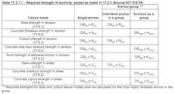
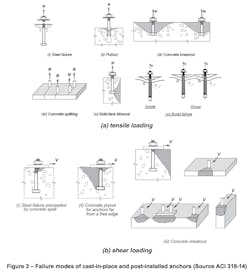
It is anticipated that engineers who have never worked with ACI 318-14 Chapter 17 (or Appendix D in previous versions of ACI) may have questions and will need some time to get acclimated with the nuances of a proper anchor design. While at first the equations may seem intimidating, ACI has done a good job to link the various equations with the potential failure modes of the various anchor systems. The relevant failure modes are listed in ACI 318-14 Section 17.3.1 and Article 5.13.2. ACI 318-14 Table 17.3.1.1 and Figure 3 below show the various failure modes, and Table 17.3.1.1 also shows where to find the design equations in ACI 318-14 Chapter 17.
The design strength in tension and shear will be the lesser of the various tension and shear failure modes as described in Table 17.3.1.1. There are eight separate failure modes, five of which are in tension. However, depending on the type of anchor chosen, not all failure modes are relevant. Cast-in-place, undercut and expansion anchors do not need to consider bond strength. Adhesive anchors do not need to consider pullout strength. Post-installed anchors do not need to consider side-face blowout at all, and it is only considered for cast-in-place anchors when they have a deep embedment and are nearby the concrete edge. Steel strength is typically given for a specific anchor, which means there are typically two equations in tension (concrete breakout and either pullout or bond strength) and shear (concrete breakout and pry-out) that may need calculation effort.
The strength reduction factors, , that are used to determine the design strength are noted in Section 17.3.3, and are applicable when the load combinations of ACI 318-14 Section 5.3 are followed. The LRFD Bridge Design Specifications utilize load factors per Section 3. Article 5.13.2.2 states that the strength reduction factors in ACI 318-14 Section 17.3.3 are applicable when the load combinations of Section 3 are used as well. Thus, there are no additional adjustment factors when an anchor design per ACI 318-14 Chapter 17 is performed.
Sustained load conditions
One adjustment that Article 5.13 made to the ACI 318-14 Chapter 17 design is regarding the reduction factor for sustained load check on the bond strength. In addition to the bond strength calculation in section 17.4.5, an additional check is required by ACI with the following equation:
0.55 Nba > Nua,s (ACI 318-14 Eq. 17.3.1.2)
Nba is determined from Eq. 17.4.5.2, and Nua,s is the factored sustained tension load. For example, if you have a load combination that includes dead, live and wind loads, but only the dead load and live load are long-term sustained loads (will remain constantly loads over the service life of the anchor) and the wind load is only a short-term load, Nua,s only needs to consider the dead and live load for this sustained load check.
The 0.55 factor in this equation for ACI considers a 50-year sustained load at 70° F or 10 years at 110° F. Article 5.13.2.2 requires that the factor 0.55 is replaced with 0.50. This is based on a recommendation for a 100-year sustained load at 70° F or 20 years at 110° F.
Seismic design requirements
ACI 318-14 Section 17.2.3 has comprehensive instructions for seismic design, including considerations of brittle and ductile failures of the anchor systems. Section 17.2.3.1 states that these additional seismic considerations must be satisfied when the building is assigned to a Seismic Design Category (SDC) C, D, E or F. Since the LRFD Bridge Design Specifications utilize a different seismic category system, Article 5.13.3 explains that the ACI 318-14 Section 17.2.3 provisions shall apply to structures in Seismic Zones 2, 3 and 4 specified in Article 3.10.6. No other adjustments to the design are needed.
Controlling breakout
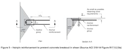
For anchor groups or anchors near an edge, the concrete breakout will generally control the design in tension or shear. To maximize the design strength, the engineer can consider additional reinforcement to preclude the concrete breakout failure mode entirely and replace this with the design strength of the anchor reinforcement. Primarily used with cast-in-place anchors, as it may be difficult to locate the reinforcement for a post-installed anchor, proper reinforcing can be an effective way to make sure that concrete breakout is not a limiting failure mode. Section 17.4.2.9, for tension (see Figure 4 below), and Section 17.5.2.9, for shear (see Figure 5 below), describe this method and provide some reinforcing details to consider.
Product qualification and evaluation and design software
As mentioned above, both ACI 318-14 Chapter 17 and Article 5.13 require that post-installed anchors have testing and published technical data per ACI 355.2 (for undercut and expansion anchors) or ACI 355.4 (for adhesive anchors). Neither ACI nor AASHTO have product evaluation departments to verify that post-installed anchors from anchor manufacturers have testing and production quality-control procedures that comply with ACI 355.2 or ACI 355.4.
However, there are third-party evaluation services that have published evaluation reports for post-installed anchors for many years. The American National Standards Institute (ANSI) has an accreditation program, ISO/IEC 17065, which is a conformity assessment program permitting bodies to certify products, processes and services. Two of the main conformity assessment bodies that are ANSI accredited and have evaluation reports for post-installed anchors are:
- ICC Evaluation Services (www.icc-es.org); and
- IAPMO Uniform Evaluation Service (www.iapmoes.org).
Both above evaluation service companies will review the test data from an independent, accredited test facility, and will issue the technical data that is in conformance with the ACI 355 test programs. In addition, they will review the manufacturing quality control for the anchor products to make sure that any product that has been evaluated will perform to the load level that has been published in their evaluation report. Engineers and building officials working on projects following the AASHTO regulations should become familiar with these evaluation service bodies and the product evaluation reports.
In addition to published technical data available from third-party evaluation services, most post-installed anchor manufacturers will provide software for their anchor products with the data taken directly from the evaluation reports. In this way, the time to create a proper design in accordance with ACI 318-14 Chapter 17, and now Article 5.13, has decreased tremendously over the years.
Summary
Cast-in-place and post-installed anchors have been used extensively on road and bridge projects for many years. ACI 318 has had LRFD provisions for anchor designs since 2002, and now AASHTO also has incorporated these design provisions into the revamped Article 5.13 of the reorganized Section 5 of the AASHTO LRFD Bridge Design Specifications, 8th Edition. Except for the adjustment to the sustained load-reduction factor from 0.55 to 0.50, Article 5.13 is a copy of Chapter 17 which aligns these two reference codes. Third-party evaluation services such as ICC-ES and IAPMO UES are publishing technical data based on ACI 355 test criteria, and most post-installed anchor manufacturers will provide software for their products with the data taken directly from the evaluation reports. Since ACI 318 anchor designs have been around for many years and since engineers may have already been exposed to these LRFD design provisions, it will hopefully be a smooth transition for anchor designs under the new Article 5.13 of the reorganized Section 5 of the AASHTO LRFD Bridge Design Specifications, 8th Edition.
------------------------
About the author:
Gamache is manager of approvals and project engineering / anchors for Hilti North America. He is responsible for creating the technical data for the Hilti North American Product Technical Guide, Vol. 2, for Anchor Fastening, and publishing external evaluation reports such as ICC-ES ESR’s. He can be reached at [email protected].
