By: Preston D. Vineyard, P.E., and Ruchu Hsu, P.E.
The Port Authority of New York and New Jersey (PANYNJ) is America’s eastern front door. It is the largest container port in the eastern U.S. and the third largest in the country.
The PANYNJ owns and manages the port system. Port Newark is one of the container terminals in the New York port. In 2011, PANYNJ restructured the lease of its major tenant, Port Newark Container Terminal (PNCT). The revised agreement calls for a 20-year extension of PNCT’s existing lease through 2050, subject to PNCT’s investment of $500 million and an expansion from 180 to approximately 287 acres to accommodate the additional freight volume that is expected.
The PANYNJ will invest more than $600 million in the expansion of the ExpressRail system, which brings ship-to-rail service to the container terminals. When completed, ExpressRail will have the capacity to move 1.5 million cargo containers a year. With the significant expansion of its ExpressRail system and enhanced inland connections, the PANYNJ is advancing its role as the gateway of choice for speeding cargo to a growing number of destinations in the Midwest, New England, Canada and beyond.
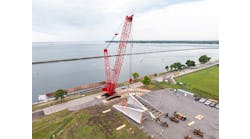
As a part of the ExpressRail expansion, improvements are being made to the Corbin Street Intermodal Rail Support Facility. One improvement is a new flyover bridge that spans Corbin Street (a four-lane arterial street) and directly connects the railroad yard to the container terminal. In its current configuration, container trucks must cross the busy Corbin Street and railroad tracks to move the containers between the ships and the trains. This not only slows down the container movement but also increases congestion of the already busy Corbin Street. The new flyover is a dedicated bridge for the PNCT operations, and the traffic on the bridge will primarily be yard tractors pulling container trailers of various lengths between the container terminal and the railroad yard.
Parsons Brinckerhoff (PB) was retained by the PANYNJ to provide final design and construction support services on the flyover bridge, with the exception of the geotechnical engineering, which was performed by PANYNJ itself. The construction bid was let on March 8, 2011. George Harms Construction Co. was awarded the project for a bid of $21.4 million. The construction of the bridge was completed in December 2012.
Skill with a horseshoe
The geometric constraints of the site required a sharply curved bridge with a centerline radius of only 169 ft. The bridge continues on a tangent alignment to meet the abutments, which results in a 1,037-ft-long horseshoe-shaped elevated structure. The bridge connects to the PNCT by way of a 375-ft-long east ramp structure consisting of modular retaining walls supported on a geogrid-structural mat that is founded on timber piles. A 126-ft-long ramp structure consisting of retaining walls supported on a concrete slab founded on steel pipe piles connects the bridge to the PNCT on the west side. The elevated curved structure consists of two 18-ft lanes with 3.5-ft shoulders. The wider 18-ft lane widths, along with a roadway deck cross slope of 3.4%, assists the tractor-trailers in navigating the tight curve of the flyover. The lanes transition from 18 to 12 ft on the approach ramp tangent sections.
There are a number of constraints at the site including a Federal Aviation Administration (FAA) ground radar tower, Corbin Street and the active railroad tracks. Additionally, there are numerous utilities at the site including fiber-optic cables for the FAA radar tower, fuel pipelines, a 30-in.-diam. gas main, an electrical conduit bank, 18- and 36-in.-diam. drainage lines, a 24-in.-diam. water main and overhead telephone lines. These constraints dictated the locations of the piers and span lengths for the superstructure as well as the type of foundation to be used. The site constraints also dictated construction methods, since delivery of material to the site, construction activities and superstructure erection must be performed in a manner that limits impact on existing operations. To minimize the foundation footprint, single-column hammerhead piers supported by single drilled shafts were selected.
Design of the new flyover structure presented many design challenges. However, this article primarily focuses on the design of the curved spans. The curved portion of the flyover consists of seven continuous spans totaling 536 ft in length. The structure curves a total of 183°, which results in a horseshoe shape. The horseshoe shape and sharp radius of curvature induces different behavior compared with a typical curved-girder bridge. As a result, an innovative controlled-floating-bearing system was developed in order to accommodate thermal expansion and contraction. Extensive analyses were conducted to select the optimal center of thermal movement in order to determine the alignment of bearing guides and to allow the bridge to freely expand and contract. The controlled-floating-bearing design minimizes the number of expansion joints, which not only simplifies the construction but also minimizes future maintenance.
Staying clear
Because of the numerous site constraints, including active railroad tracks and underground utilities, it was critical to minimize the overall foundation footprint of the new Corbin Street flyover. The solution that provided the smallest substructure footprint utilizes single-column hammerhead piers supported by single drilled shafts. The drilled shafts for the project extend through the soil deposits and utilize rock sockets to achieve their capacity.
As previously mentioned, the project site also contained an FAA ground radar tower. The ground radar system is critical for safe and uninterrupted operations at Newark International Airport. Construction of the proposed Corbin Street flyover structure required the use of heavy construction equipment and the installation of drilled-shaft foundations in close proximity to the radar station. It was essential that vibrations generated by the construction operations, including the installation of the drilled-shaft foundations, not adversely affect or interrupt the operation of the radar system. As a result, project-specific ground vibration limitations and vibration-monitoring procedures were required during construction. No excessive vibrations were detected during foundation construction near the FAA tower.
Here comes the curve
As previously described, the curved portion of the superstructure consists of seven steel I-shaped plate girders, which are continuous over seven spans of various lengths. The girders are composite with a 9½-in.-thick reinforced concrete deck. All the curved steel girders have a 4 ft 6 in. constant-depth web with variable dimension flanges. The steel I-girders were a suitable solution for the Corbin Street flyover since they could provide a shallow superstructure that could accommodate the sharply curved geometric requirements.
The pier locations were dictated by the numerous constraints of the existing conditions. The resulting spans were unequal in length. Most notably, the 130-ft-long span over Corbin Street is 1.5 to 2.5 times longer than other spans, which increased the complexity in predicting and analyzing the curved-bridge responses.
The curved radius of 169 ft along the bridge centerline nearly reached the extreme limit set by AASHTO Guide Specifications (1993) of 150 ft. The sharp horizontal curvature significantly increased inherent torsion and warping in curved girders. Because of the sharp curvature, top and bottom lateral flange bracing was necessary. The lateral flange bracing created a pseudo-closed section, which greatly increased the superstructure’s torsional capacity to resist the forces induced by the curvature.
Due to the complexity of the structure, a refined structural analysis was warranted. The global analysis of the bridge was carried out using a 3-D structural model, including explicitly modeled foundation elements with nonlinear springs to simulate the soil properties. The global analysis was conducted using a commercially available general analysis program. The 3-D structural model was used to simulate the behavior of the structure during various stages of construction as well as in the structure’s completed state. As with most continuous-span bridges, the concrete deck of the Corbin Street flyover was placed in multiple pours. Because of the sharp curvature and span arrangement, the flyover was particularly sensitive to the deck-casting sequence. A detailed analysis was conducted to determine a suitable deck-casting sequence that would not result in any girder uplift at the bearings. The analysis also determined the load effects, locked-in stresses and deformations of the girders, lateral bracing and diaphragms during deck placement. This analysis was critical since the effects of the deck placement can often control the design of these members.
As required by the project design criteria, any future deck replacement must take place while maintaining one lane open to traffic. Expected deck-replacement construction stages were therefore simulated and evaluated using the structural model. As expected, the governing loading case occurs when the inside half of the deck is removed and vehicle live load is present on the outside lane. The analysis confirmed that future deck replacement is feasible, and the members have been designed accordingly.
The structural model simulating the flyover in its completed state was then utilized to predict the bridge’s response to transient loads such as vehicle live load, wind load, earthquake and superimposed deformations caused by temperature variations. The bridge’s response to temperature changes is particularly unique and is discussed in more detail below.
Floating a solution
The 541-ft-long curved-girder portion of the Corbin Street flyover has been designed to have only two expansion joints. The joints are located at the points of tangency of the horizontal curvature, which coincides with piers 5 and 12. Having only two expansion joints has numerous benefits, including a reduction in future maintenance and improved structural performance. However, the relatively long unit significantly increases the thermal movement of the structure. When this thermal movement is combined with the sharp curvature, the bridge behavior is further complicated. As a result, design of the bridge essentially required controlling this thermal movement to minimize the additional loads induced by thermal restraint. Particular attention had to be paid to the thermal movement on bridges such as the Corbin Street flyover with sharp curvature. This was because the bridge translates in both the radial and tangential direction. Excessive lateral thermal forces at supports can result if only tangential movement is permitted.
Several bridge articulation configurations were evaluated during the design process. The configurations included fixing a single pier, fixing all piers and two different floating systems.
Traditional curved-girder design generally provides one fixed support (restraint to all translations). All other bearings are guided toward this fixed bearing so that they can expand and contract toward the fixed bearing. Thus, the fixed bearing becomes the center of thermal movement (CTM). For a curved bridge that has a small number of spans and is short to medium in bridge length, this approach is appropriate. However, this boundary system increases the thermal expansion length as the bridge length is increased. In addition, one fixed pier is required to resist all the structure’s lateral loads, and the thermal movement directions at the expansion joints are not tangential, but skewed. Because of its sharp curvature and long expansion length, the traditional curved-girder design articulation methodology was not ideal for the Corbin Street flyover bridge.
Providing full restraint to all translation at each pier was evaluated during the design process. This design approach relies on the flexibility of the substructure to accommodate the thermal displacements. Although this design approach is often utilized, it was not suitable for the Corbin Street flyover because of the relatively short (stiff) piers.
Since the sharply curved structure primarily translates in a radial direction, a free-floating bearing system allowing free radial displacement toward the CTM also was investigated. All thermal movements expand and contract toward the CTM. In theory, this floating system induces minimal forces due to thermal displacement since the movement is not restrained. The performance of this system relies on the accurate determination of the CTM. In the case of the Corbin Street flyover, which has numerous piers and bearings, the CTM determination was quite difficult, since the varying pier and bearing-lateral stiffness causes the CTM to shift. In addition, each bearing has a unique orientation to guide it toward the theoretical CTM, and the shifting CTM causes frequent engagement in the bearing guides. Similar to the traditional bearing alignment, the free-floating bearing system also has skewed thermal movement at the expansion joints. Because of the complex bearing orientation and the resulting skewed thermal movement at the expansion joints, the free-floating bearing system was not practical for this structure.
To achieve the goal of minimizing the thermal forces on the structure as well as to provide a bearing system that is easy to construct and maintain, a controlled-floating-bearing system with simple guided elastomeric bearings was developed for the Corbin Street flyover. The controlled-floating-bearing system is similar in concept to the free-floating system, with the exception of the boundary conditions at the expansion joints. When the tangential displacement at the expansion joints is restrained, the CTM is located at the center of the curvature. All thermal displacements in the controlled-floating-bearing system are tangential to the curvature at any given location. All bearings are oriented to the concentric center of the bridge curvature and aligned to be perpendicular to the pier to simplify construction. The tangential displacement at the expansion joints is restrained by use of a tangential bumper system, which is described in detail below.
To achieve the controlled-floating-articulation concept, longitudinal bumpers are required to resist the tangential restraining forces at the expansion joints, but still allow free translation in the radial direction. The bumpers consist of a steel bracket mounted to a concrete corbel extending from the pier cap and a steel tongue bolted to the bottom of the center girder. Elastomeric bumper pads consist of vulcanized steel plates, which bolt to the bracket on the pier. Stainless steel plates are attached to the bumper pad and the steel tongue. As the bridge expands, the tangential force from the superstructure engages the tongue and bracket. The elastomeric bumper pads evenly distribute the force to the stainless steel plates, which provide the sliding surface for the radial expansion.
Since the controlled-floating-articulation system allows radial displacement, the expansion joints and utility conduits in the barriers also must accommodate the radial displacement. A conventional strip seal expansion joint system was selected and sized to accommodate the nearly ±1 in. of radial displacement. In the case of an extreme event that results in very large radial displacements, the rubber strip seal gland may overextend and tear. A removable expansion joint rail system, which was provided by PANYNJ, simplified the replacement of the rubber gland. In order for the rigid conduits to accommodate the radial movement, the conduits extend out of the deck slab and transition to a flexible metal conduit.
In addition to allowing the structure to accommodate thermal displacements, the bearing and bumper system also must transfer wind and seismic forces between the superstructure and the substructure. In the case of the Corbin Street flyover, the 56 elastomeric bearings located along the curved structure provided lateral support. For added support, additional bearing guides were provided at each pier. R&B
About The Author: Vineyard and Hsu are with Parsons Brinckerhoff.


