Taming the beast
The word Tanana means “trail river.” The new Tanana River Bridge in Salcha, Alaska, a small community located south of Eielson Air Force Base, provides a trail across the river—a vital connection to 1 million acres of U.S. military training facilities in Alaska. Construction of the bridge marks the completion of the first phase of the Alaska Railroad Corp.’s (ARRC) Northern Rail Extension, a project that will create an 80-mile rail network between North Pole and Delta Junction, Alaska. The extension provides a safer, all-weather transportation option and gives the military improved, year-round access to training facilities south of the river that previously were accessible only by ice roads during winter.
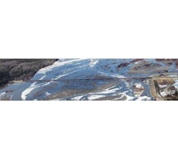
The bridge crosses the glacier-fed, braided Tanana River at a remote site with potentially active seismic faults. In addition, the design had to account for wind, stream flow and debris pressures, river bed scour, sheet ice and severe flooding. Moreover, temperatures in the area range from occasional highs near 90°F to lows near -70°F. All of these facts weighed heavily on the design scheme.
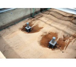
The University of Illinois at Urbana-Champaign’s Ven Te Chow Hydrosystems Laboratory constructed a 3-D model using 11 tons of crushed walnut shells to mimic streambed material, conducted testing and provided analysis of the Tanana River Bridge piers.
Remote collaboration
The ARRC contracted the project using the construction manager/general contractor process. Hanson Professional Services was part of a team that included Kiewit Infrastructure West Co., Anchorage, Alaska, as general contractor and HDR Alaska Inc., Anchorage, as ARRC’s consultant for permitting, hydrology, land acquisition and construction management. Hanson’s subconsultants included Shannon & Wilson Inc., Fairbanks, Alaska, responsible for geotechnical engineering, foundation construction recommendations and pile-driving observation; JE Fuller/Hydrology & Geomorphology Inc., Tempe, Ariz., responsible for 2-D modeling; the University of Illinois at Urbana-Champaign’s (UIUC) Ven Te Chow Hydrosystems Laboratory, which constructed and conducted a 3-D physical hydraulics model; and Northwest Hydraulic Consultants of Edmonton, Alberta, Canada, responsible for guidance regarding ice load design parameters. HDR’s subconsultants included PDC Inc. Engineers of Fairbanks, Alaska, responsible for surveying and HRV Inc., Moon Township, Pa., responsible for third-party quality assurance for the girder fabrication.
Such a myriad of contributors is one aspect defining what is known commonly as a megaproject.
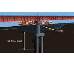
The design team conducted extensive hydraulics modeling to determine how the river flows, soil conditions, how ice and timber jams might affect the bridge and create various scour conditions. The scour was expected to be more than 50 ft deep at the piers.
Guiding design via 3-D
Before the design process began, the design team conducted extensive hydraulics modeling to determine how the river flows, its soil conditions, how ice and timber jams might affect the bridge and create various scour conditions. The scour was expected to be more than 50 ft deep at the piers. Geotechnical analysis showed that the bridge’s foundation piles would not have the support of bedrock, which complicated matters.
With the number of variables being addressed, analysis of an initial one-dimensional hydraulic model provided some assurances, but not enough. The team then asked Dr. Robert Carlson, a former consultant with Hanson and a professor emeritus at the University of Alaska-Fairbanks, to get involved. Based on his decades of experience providing Alaskan river engineering, including the Tanana River, Carlson advised ARRC that more modeling was necessary. The team moved forward with 2-D modeling, but the data and analysis still weren’t able to answer all of the team members’ questions and concerns.
At this point, the team felt it would be prudent to proceed with a more in-depth, physical model. While 3-D modeling isn’t required for railroad bridges, ARRC agreed with Hanson’s recommendation to create a 3-D physical model to provide more detailed data.
The UIUC’s Ven Te Chow Hydrosystems Laboratory constructed a 3-D model using 11 tons of crushed walnut shells to mimic streambed material, conducted testing and provided analysis of the bridge piers. The 3-D modeling helped the team confirm its design approach for scour.
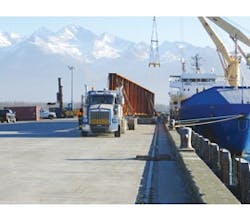
One of the major challenges of this project involved transporting by truck 80 165-ft-long girders 330 miles on the Richardson Highway from the port of Valdez, Alaska, to Salcha, Alaska. The girders were fabricated in China and shipped to Alaska.
Dual-use bridge
The long-term plan to use the bridge to support rail traffic and military vehicles was a major factor in designing the bridge deck. The team studied concepts, including the construction of independent superstructures that were supported on a shared foundation. The preferred solution was to design a deck similar to a grade crossing over the full length of the bridge. The challenge with this approach was to minimize weight while providing support for wheel loads and allowing snow and ice to drain from the rail trough.
While the bridge was designed to serve railway and roadway traffic, the bimodal deck part of the design was removed during the cost-estimating portion of this project and after the final design was completed. (It will be installed during a future phase.) A steel ballast pan was constructed in its place to allow for vehicle access. Design of the deck elements considered AASHTO load vehicles and military load classification vehicles used for transporting tanks and Stryker-type combat vehicles.
The design criteria established for the project was primarily based on the American Railway Engineering and Maintenance-of-Way Association’s (AREMA) Manual of Railway Engineering. This guideline was supplemented with segments from the AASHTO LRFD Bridge Design Specifications and the Military Non-Standard Fixed Bridging Manual FM 3-34.343. Additional customization included the combination of various scour conditions with applicable design loads and acceptable service-load deflections for numerous load cases.
Five different scour combinations were considered based on the presence of ice or debris and use of seismic design parameters. Flows in the Tanana River often include the release of large sheets of ice during the area’s spring thaw and logs nearly 90 ft long that could potentially collide and jam against the bridge piers. The design team also considered the site’s high seismic forces, including areas with potentially active faults. The Denali Fault generated a magnitude 7.9 earthquake in 2002; a 9.2-magnitude earthquake happened east of Anchorage in 1964; and three magnitude 7.0 earthquakes have occurred within 50 miles of Fairbanks in the last 90 years.
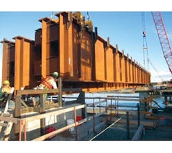
The steel superstructure of the bridge consisted of 12,650 tons of steel. This included 11-ft by 4-in.-tall girders that each weighed more than 145,000 lb. Construction crews used two crane lifts to set the 80 girders into place.
Selecting the right piers
Initial efforts focused on the conceptual options for the bridge’s piers because those elements were identified as one of the primary cost drivers. The access requirements for foundation construction drove the selection of the pier type. The design and construction team wanted to minimize the need for a cofferdam to save time and money. The need for increased pier stiffness to resist loads during deep scour governed the design. The conventional pier type, which used 6-ft-diam. pipe piles and was constructed with a cofferdam approach, was utilized for the bridge.
The superstructure options revolved around deck-plate girder-type spans from the beginning. This type of span was preferred by the ARRC over trusses and through-plate girders. While the basic need was to maximize the span length to reduce the number of piers, the ARRC also wanted to avoid field splices, so the span lengths meeting these criteria were thought to be in the 150-ft range. Preliminary design was completed on spans between 150 ft and 173 ft, using three or four girders. Concerns with fabricating to fracture-critical criteria removed the three-girder system from consideration. High-level design analysis and subsequent construction cost estimating were completed to determine the low-cost combination for span length and pier size. When combined with preliminary hydraulics analysis around a total bridge length of 3,300 ft, the final solution resulted in 20 165-ft-long spans.
Overcoming logistical issues
Logistics were a major factor affecting construction. The remote location required that nearly all materials and equipment be shipped by ocean barge and transported to the site by truck. Getting access to the pier locations across the 3,300-ft-long bridge determined the project schedule.
Constructing a combination of earth causeways over the dry river sections and steel-trestle structures over river braids or channels provided access. Each spring around May, the ice would break up and move its way down the river. The steel trestles were not stiff enough to withstand the ice loads and had to be removed before the ice breakup. Two to three months of fair weather were lost each year between April and June because of the removal and reconstruction of the causeway and trestle access. The overall schedule required access to be constructed in the summer of 2012, before being removed and reinstalled in 2013. The causeway and trestles were removed for the final time during spring 2014.
Another logistical challenge involved girder fabrication in China. This approach resulted in additional quality-assurance and quality-control activities to confirm that delivered materials met the contract documents. Third-party inspectors observed fabrication full time on-site, and these efforts were supplemented by occasional site visits by representatives from the ARRC and Kiewit.
The girders were transported in two shipments to the port of Valdez, Alaska, before being loaded on trucks for delivery to the project site. The challenge was transporting 80 165-ft-long girders—one girder per truck—330 miles over Richardson Highway. Each girder weighed more than 145,000 lb. When the girders arrived at the project storage yard, workers connected them as pairs with bolted diaphragms and lateral bracing elements before their final transport and erection onto the piers.
Kiewit completed the cofferdam design and construction, allowing up to five piers to be under construction at any one time. This approach afforded reduced construction time with repeatable elements and efficient use of equipment. Cofferdam construction essentially followed installation of the causeway and trestle with different work items completed over two daily shifts during peak construction periods.
The pile-driving operation was identified as having a higher element of risk behind it because of the lack of bedrock and a test pile program. The pile design was based on the use of 72-in.-diam. steel pipe piles with ¾-in. wall thickness that were to be driven approximately 140 ft below the pile cap. There was a small risk that piles would be driven to the maximum available length but not demonstrate acceptable capacity. Ultimately, the piles required approximately 10% more length than planned. After testing was completed on 13 pier piles over the length of the bridge, the pile capacity was confirmed as meeting the ultimate design value of 3,795 kips.
Doing a cold-climate pour
Because of the tight schedule for completing the bridge in two work periods, concrete had to be placed during the winter. Kiewit made several types of provisions to enclose and heat the inside of the cofferdams and also worked with the local concrete supplier to allow concrete mixing to occur in winter periods, when the batch plant normally was shut down. Temperature monitoring was done on the concrete foundations to confirm that internal and external temperatures fell within specified limits.
Concrete placement typically was done in three phases: pile infill, pile cap and the column and pier cap. Because of the number of identical piers being fabricated, Kiewit used custom forms for the column and pier cap that consisted of two large pieces with a vertical joint down each side. The formwork was supplemented with custom templates placed on top to help improve locating voids for anchor bolts and the bearing elevation. Reinforcing cages also were prefabricated in the yard for the column and pier cap sections before being erected and tied together in the formwork.
Superstructure erection was completed after a series of planning meetings and formulating the erection plan, including a thorough review of crane capacities. Girders were erected in pairs using a double-crane pick with a special swing sequence to minimize the required crane radius. After a few spans were initially set, workers determined that several spans could be installed each day. Follow-up work included bolting the diaphragms that connected the girder pairs and bolting on the steel deck, guardrail and walkway with handrail.
The Tanana River Bridge was officially opened Aug. 5, 2014, during a ribbon-cutting ceremony. At 3,300 ft, the 20-span steel bridge is Alaska’s longest and was completed for $187 million, $1 million under budget. R&B
