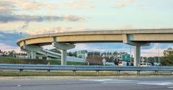
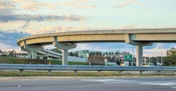
The U in curved
When it comes to bridge design, advancements in technology often take a long time to be widely accepted. After all, if a technique has been proven to work, why reinvent the wheel?
For some time, this has been the thinking when it comes to spliced girder bridges. Traditionally, spliced girder bridges have been used for continuous structures to facilitate longer spans. Until recently, this technique was limited to use for straight concrete I-girder sections. With the introduction of new concrete casting technology and construction techniques, spliced U-girder technologies now allow the option of curved bridges.
One example of this technology and technique in use is the complete redesign of the interchange between I-95 and S.R. 202, also known as JT Butler Blvd., in Jacksonville, Fla. The project owner, the Florida Department of Transportation (FDOT), found it was best to implement this new spliced U-girder technology due to the time and cost savings seen in other projects that implemented it.
FDOT found it best to use new spliced U-girder technology for the sake of time and cost savings on the project.
The first of the flyovers
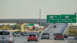
The intersection of I-95 and JT Butler Blvd. is a major traffic interchange south of downtown Jacksonville. I-95 carries the flow of north and south traffic through the heart of Jacksonville, while JT Butler Blvd. carries east and west traffic to the beaches on the Atlantic Coast.
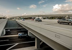
This project consisted of four total bridge structures, new ramp configurations, new highway alignments and roadway widening of both I-95 and S.R. 202.
For this design-build project, Summit Engineering Group, a Modjeski and Masters company, served as both the design engineer of record (EOR) for the Flyover 1 bridge and the contractor’s engineer for all four bridge structures, a unique dual role in a project of this nature.
Summit, which is headquartered in Colorado, has implemented spliced precast girder technology on numerous constructed bridges. This experience assisted FDOT in its EOR selection process, since it was the first time the agency had leveraged this technology.
The main goal of the project was to ease traffic congestion at this major interchange. Flyover 1, the main bridge of the project, is a new ramp designed to alleviate the traffic jams and traffic safety issues caused by the previous configuration. It carries traffic from SB I-95 to EB JT Butler Blvd.
Prior to completion of the Flyover 1 bridge, traffic from SB I-95 going to EB S.R. 202 exited the highway to a traffic light intersection. Unfortunately, during peak travel times, traffic would back up onto I-95 for up to a mile, creating long commute times and safety issues for the traveling public.
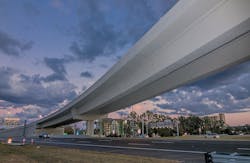
The new Flyover 1 bridge is a seven-span, 1,342-ft-long structure. The bridge will help to provide a continuous flow of traffic, allowing for a direct merge without stopping. The new bridge was constructed over three major traffic crossings, SB I-95, NB I-95 and WB S.R. 202, and FDOT required that all lanes remain open to traffic during construction. Only overnight lane closures were allowed, providing six- to eight-hour windows for all the construction and erection procedures that needed to occur in traffic areas.
In order to facilitate construction, the maintenance of traffic (MOT) plan was integral to the success of the project. Therefore, several traffic shifts were executed to open different areas of the project site for construction while maintaining all of the travel lanes as required by FDOT.
I-95 carries the flow of north and south traffic through the heart of Jacksonville, while JT Butler Blvd. carries east and west traffic to the beaches on the Atlantic Coast.
To accommodate the constant flow of traffic through the jobsite, several innovative features were incorporated into the bridge design.
For this project, precast pier caps were deployed at the interior piers. These locations were adjacent to traffic during construction, which meant using temporary shoring to support the formwork was not an option. These pier caps were cast by the contractor on-site with a central blockout to form a cast-in-place (CIP) connection with the column.
The precast pier caps also were used to support the pier girders during construction, helping to eliminate the need for falsework towers within the traffic zone. The pier girders were erected onto temporary falsework towers at one end and supported on the precast pier caps with large cantilevers.
Due to the geometry of the site and the active traffic lanes, minimizing the amount of falsework towers was a key component in the design of the Flyover 1 bridge. The cantilevered pier girders supported drop-in girders on strongbacks, thus eliminating the need for falsework towers at these locations.
The strongbacks connected to the girders through a partial-depth diaphragm, supporting them from the top. This strongback configuration allowed the team to supply the minimum vertical clearance over traffic since there was no hardware from the strongbacks projecting below the bottom surface of the girders.
Span 6 of the Flyover 1 bridge is the second-longest span in the structure, measuring 228.92 ft. Girder shipping weights limit the maximum piece length to 100 ft for pier girders and 115 ft for drop-in girders. Due to the pier locations and site geometry, a single drop-in girder could not span between pier girders.
To overcome this geometric constraint, a temporary straddle bent was designed to support two drop-in girders at the central splice location in this span. The straddle bent spanned approximately 70 ft to provide clearance for three traffic lanes.
Some of the temporary works for the project, while out of traffic lanes, were still within the envelope requiring crash protection. Due to this requirement, a crash protection system was designed.
Prior to the completion of the Flyover 1 bridge, traffic from SB I-95 going to EB S.R. 202 exited the highway to a traffic light intersection.
This system was installed prior to erecting girders for any falsework support leg within 10 ft of a traffic lane. To construct this system, precast concrete traffic barriers were combined with a steel “rub rail” to prevent a truck from overturning over a barrier and crashing into the falsework.
The crash protection was required at two locations: A falsework tower adjacent to I-95 and the north tower support of the straddle bent adjacent to S.R. 202.
The superstructure of the Flyover 1 bridge is where the spliced U-girder technology was implemented. The structure was designed using time-dependent load-history analysis with each stage of construction included in the analysis. During this, the structure is aged to 30 years to account for long-term creep and shrinkage effects.
The superstructure is composed of two girder lines of 84-in.-deep precast U-girders spaced at 23 ft 9 in. center to center. To minimize form changes, both the left and right girders were designed to be cast at a 1,110-ft radius, which was the average radius of the two girder lines.
The precast girders are comprised of three different girder types: end girder, pier girder and drop-in girder. All the girders are designed with 8-in.-thick end diaphragms to provide torsional rigidity for handling and for even load distribution into the CIP splices.
The end and drop-in girders have two tendons in the bottom slab to control positive moment stresses and to allow handling from the lifter at the girder ends during erection.
The pier girders were designed with two tendons in the bottom slab and two tendons in the top flanges. The bottom slab tendons control positive moment stresses and allow handling from the lifter at the girder ends during erection. The top slab tendons provide reinforcement and stress control for the large cantilevers of the pier girders during erection.
Due to the tight geometric constraints of the jobsite and the requirement to keep all traffic lanes open, construction staging was a very important part of the superstructure design. With the unique position of being the EOR for Flyover 1 and the specialty construction engineer for the contractor, coordinating the means and methods of the contractor with the superstructure design was a seamless process.
The main goal of the project was to ease traffic congestion at this interchange.
All in one
In addition to implementing new technology, this project also utilized a non-traditional team structure.
Typically, for a highway project like this one, agencies such as FDOT will have one point of contact for the structure design and another for the construction and erection engineering.
By serving both roles on this particular project, Modjeski and Masters was able to leverage intimate knowledge of both the design and construction, making only one point of contact necessary. This helped to streamline communication and coordination, even with some staff being physically located in Colorado while working on the project in Florida.
The project timeline also benefited from one engineer serving as EOR and the contractor’s engineer. Developing a temporary falsework design to maintain traffic in conjunction with the structure design produced significant time savings. Splitting the design drawings into a foundation package and a sub/superstructure package also helped to break ground on the project earlier.
Once the foundation designs were complete and approved, construction on the foundation was allowed to begin prior to completion of the superstructure design. Typically, when an agency has two separate firms taking on these roles, construction is not able to begin until all designs are finished and approved. While deadlines can be set to make sure all parties stay on the same page, you can never predict obstacles that could get in the way and prevent meeting these targets, often leading to delays.
While this technology and role provided numerous benefits, there were still obstacles to overcome.
The project consisted of four total bridge structures, new ramp configurations, new highway alignments and roadway widening.
Learning on time
One of the biggest challenges when instituting a new technology is that there is not a common level of understanding between all parties. In this case, before construction could begin, there was a period of education and adjustment to familiarize all stakeholders with the technology being implemented.
Once construction began, there was still a learning curve for those who had not previously worked on a project using precast spliced U-girder technology. Although the learning curve has the potential to slow down the initial phases of a project, implementing spliced precast girders as opposed to traditional techniques in this situation still resulted in overall time and cost savings for this project.
The design and construction of the SB I-95 to EB S.R. 202 Flyover bridge is a prime example of the versatility of precast concrete construction. Precast concrete designs can provide innovative and unique solutions to many bridge design challenges. The curved, precast post-tensioned U-girders are a powerful and cost-effective method of alleviating traffic congestion and safety issues, providing a beautiful aesthetic with comprehensive engineered solutions.
