By: Daniel Baxter, P.E., S.E., and Krista Stippelmans
When the I-35W Mississippi River Bridge collapsed tragically in Minneapolis in 2007, the state’s legislature wasted no time in passing legislation in 2008 for a 10-year Bridge Replacement Program focused on bridges classified as either structurally deficient or fracture critical.
According to Chapter 152, a provision of the law that includes the Trunk Highway Improvement Program, work on bridges in the program must be under contract for repair or replacement by June 30, 2018—and the new bridges must include a load-path-redundant design.
The load-path-redundant design requirement didn’t represent a monumental design challenge regarding the replacement of most of the state’s structurally deficient bridges. Then again, of the structures to be replaced, most didn’t offer a uniquely designed steel riveted cantilever through-truss with rare, once-cutting-edge deck trusses. Most were not considered by the Minnesota Department of Transportation (MnDOT) as the state’s “only surviving example of a pre-1946 cantilever through-truss,” with eligibility for inclusion on the National Registry of Historic Places.
Therein lay the engineering design challenge for MnDOT and its engineering and construction partners with the one-of-a-kind Minnesota Bridge No. 5900, also known as the historic Winona Bridge.
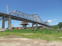
The Winona Bridge, completed in 1942, carries Trunk Highway 43 over the Mississippi River and provides access for truck traffic from Wisconsin to the port of Winona. Extending 2,282 ft between abutments, the main 933-ft span is a steel through-truss, with two deck truss spans and multiple concrete T-beam spans on the south approach, and four deck truss spans on the north approach.
This iconic bridge also features two parallel trusses with many fracture-critical steel tension members, which means the fracture of any one of these members could result in a collapse of the entire structure. While the Winona Bridge had become a beloved historic landmark to the city, it also had deteriorated significantly since a prior rehabilitation in the mid-1980s.
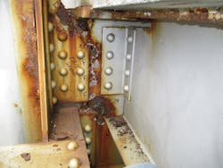
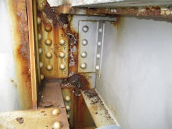
Pack rust had accumulated on the portions of the truss below the level of the roadway, and the increasing deterioration of the deck truss approaches ultimately forced MnDOT to restrict the maximum truck weight on the bridge through load posting. Consequently, the bridge was included in the Tier 1 list of the Chapter 152 legislation and Trunk Highway Bridge Improvement Program.
Figure 1. 3-D finite-element model was used during project planning.
To restore or replace?
MnDOT, in consultation with its project partners, considered both rehabilitation and replacement of the bridge, wrestling with striking the right balance between the federal laws that provide for protection of the nation’s historic structures and the community’s desire to preserve a historic icon, while ensuring long-term public safety and fulfilling the intent of the Chapter 152 legislation. Ultimately, MnDOT decided, in essence, to restore and replace.
The plan: To construct a new parallel bridge to accommodate inbound traffic from Wisconsin and rehabilitate the Winona Bridge to allow for two lanes of outbound traffic. The new southbound bridge would be constructed first, after which all traffic would be shifted from the old bridge to the new bridge to allow for the rehabilitation of the existing historic Winona Bridge—including the discrete addition of structural redundancy.
The decision to rehabilitate rather than replace the original Winona Bridge brought with it a number of significant challenges. For instance, the MnDOT Cultural Resources Unit (CRU), working with the Minnesota Historic Preservation Office (MnHPO), had to make a determination whether any necessary alternations to the bridge would have an adverse effect on the historical character of the bridge.
A “no adverse effect” determination was a commitment MnDOT made within the project Environmental Assessment. Any significant impact would compromise the iconic nature of the bridge and would create a lengthy delay to accommodate the completion of an Environmental Impact Statement. The rehabilitation also would have to satisfy the intent of the Chapter 152 legislation regarding redundancy requirements concerning fracture-critical members, while also allowing for the removal of load restrictions. Those latter requirements would prove most challenging to satisfy without significantly altering the historic appearance of the bridge.
Picking the team
To clear these significant project hurdles, MnDOT decided to use the Construction Manager/General Contractor (CM/GC) method of project delivery for the first time in the state’s history. The CM/GC delivery method allows for an integrated approach to planning, design and construction. Using this approach, the owner of the project selects an experienced contractor and pairs it with a designer at the inception of project design. The contractor then prepares cost estimates using the designer’s milestone plan set. These estimates then are compared with those prepared by an independent estimator.
For the Winona Bridge project, CM/GC delivery allowed the design team to work closely with the contractor during design, an opportunity usually reserved for those using a design-build delivery approach. CM/GC also gave MnDOT greater control over design criteria and decisions, which typically only occurs with design-bid-build contracting.
At the onset of project final design, MnDOT selected Ames Construction to serve as general contractor. Headquartered in Burnsville, Minn., Ames Construction has a long history of successfully completing large-scale projects in the state. MnDOT then chose Michael Baker International to serve as final design engineer of record for the bridge rehabilitation due to the engineering firm’s extensive experience evaluating and rehabilitating other fracture-critical structures.
MnDOT ultimately settled on both restoring and replacing the Winona Bridge.
Building an addition
One of the most critical challenges with the rehabilitation design was to address Chapter 152 requirements concerning the fracture-critical steel tension members. The design team quickly determined that providing load-path redundancy to the truss itself would not be feasible. Adding an additional truss line or any other independent structural system to supplement the existing through-trusses, the team concluded, would prove cost-prohibitive and would irreparably mar the historic character of the bridge. Instead, the design team took advantage of the cross-sectional dimensions of the existing through-truss tension members to add internal redundancy.
While the Federal Highway Administration still considers tension members with internal redundancy to be fracture-critical, a member with internal redundancy is designed to remain intact if any one component of the cross-section fractures. For the Winona through-truss, providing internal redundancy to the tension members would satisfy Chapter 152 requirements by preventing collapse in the event of a fracture, together with documenting why providing load-path redundancy was not feasible.
Upon inspection, MnDOT and the rehabilitation team found that the existing deck trusses were beyond repair. To maintain the historic character of the river crossing as a whole, MnDOT worked with its project partners on various approach-span replacement alternatives and ultimately elected to replace the deck trusses in-kind with new deck trusses. One important benefit of the new deck trusses over the old: All tension members would be designed for internal redundancy.
The existing through-trusses serve as the most prominent part of the bridge, so the design team viewed replacement of the through-truss in-kind as a less-than-desirable option from both historic and financial perspectives. Nearly all of the existing through-truss members are built-up box sections, with the top chords consisting of closed boxes, and the diagonals, verticals and bottom chords consisting of double-channel sections connected with either lacing bars or batten plates.
To create internally redundant tension chord members, the design team proposed adding plating to the top and bottom chords of the through-truss tension member as required. For the verticals and diagonals, the team would provide internal redundancy by adding high-strength steel bars inside the existing built-up box sections. The diagonals and verticals are most visible to motorists, so the team wanted to make sure any changes would be minimal to the appearance of these prominent components of the bridge.
The proposed changes to the appearance of the bridge were minor enough that, after evaluating the proposed retrofits, MnHPO concluded the changes would create no significant impact to the historic character of the structure. So the design team was granted permission to proceed.
The size of strength
To measure the strengthening required to achieve internal redundancy, the team evaluated the truss tension members for two conditions. First, the team examined the possible loss of any one component of the built-up cross-section, without considering dynamic-force effects resulting from a fracture. Second, the team examined the possible fracture of one component of the built-up cross-section, this time considering the dynamic effects of such a fracture, but with lower overall force effects. The team then computed the resistance of the members with one fractured plate removed, and compared it to the demands given by both of these load combinations.
The design team specified the plating and high-strength bars as required to provide sufficient resistance to satisfy the demands from these load combinations. Not all tension members required retrofit, as some tension chords possessed sufficient resistance to satisfy these load combinations with any one existing plate removed.
Function satisfaction
The design team accordingly investigated several issues to ensure that the high-strength bars would function satisfactorily to provide internal redundancy after a fracture. These analyses included determining the amount of load shedding to adjacent members and additional deformations as a result of a reduction in axial stiffness after fracture. The team also investigated whether existing rivets in gusset plates would fail due to differential displacements between the fractured member and connection, as well as the effects of eccentricity of the remaining steel from the member centerline, and whether the high-strength bars would engage effectively to carry load.
To answer these questions, the design team undertook a refined 3-D finite-element analysis that was integrated into the conventional 3-D finite-element model of the entire through-truss. The analysis focused on the theoretical fracture of a tension diagonal member retrofitted with high-strength bars near the quarter point of the main span over the river. This member, U13-L14, consists of two steel channel sections connected with batten plates, and was chosen because of the comparatively large area of each channel section.
The design team analyzed the possible fracture of one of the two channel sections near the U13 gusset plate, under a factored load corresponding to the loss of one component. The team modeled the remaining intact channel at the location of the fracture with an element with material nonlinear properties, ensuring that the principal stress in the remaining steel cannot exceed the yield stress.
The team modeled the rivets connecting the fractured member and the adjacent truss members to U13 and L14 with multilinear links, with the variable displacement-vs.-shear characteristics of the actual rivets used on the bridge. The four high-strength bars, located inside the two channel sections of U13-L14, were modeled with truss elements connected to anchorage and wedge plates on the top face of U13 and the bottom face of L14.
The conclusions of the analysis gave the design team confidence that the high-strength bars would function as intended to provide internal redundancy in the event of a fracture. The most heavily loaded rivets in the U13 and L14 gusset plates remained far from their maximum limits of shear and deformation in the model. The remaining unfractured channel did reach yield as anticipated, but this did not overstress the U13 gusset plate adjacent to the theoretical fracture location.
Vertical global truss displacements computed by the model at panel points 13 and 14 increased less than 1⁄2 in. compared to pre-fracture values—an increase deemed acceptable—and did not distress the adjacent truss members or connections. The design team also concluded that designing the high-strength bars with sufficient area to carry the total member force after fracture (neglecting the contribution of the members’ remaining unfractured original steel), provided sufficient axial stiffness to prevent post-fracture deformations from becoming excessive.
The design team’s rehabilitation plan also includes the strengthening of select compression members, extensive repairs to the deteriorated through-truss floor system and construction of a new deck. All diaphragms and connection plates with rust holes will be replaced in-kind. Enhanced scour-and-vessel collision protection of the existing truss piers also will be provided, since the original timber piles were not designed for vessel impact.
An example of the degradation project planners had to face in restoring the bridge.
Breaking it up
The design team took advantage of the close collaboration with the contractor afforded by the CM/GC process to ensure that the through-truss could be repaired and retrofitted for internal redundancy without any significant impact to the bridge’s historic character. By dividing the project up into several work packages, MnDOT was able to deliver the new adjacent bridge on an accelerated time schedule, and shift traffic onto the new bridge to enable rehabilitation of the iconic truss ahead of schedule. The work for the truss rehabilitation was awarded to the CM/GC, Ames Construction, with a final bid of $38.9 million for the rehabilitation of the through-truss and removal of the approach spans, with the final work package to replace the approach spans slated for a May 2017 letting.
Get ready to celebrate
As spring arrived in the Mississippi River valley in southern Minnesota, the Winona Bridge through-truss was closed to traffic, and retrofit work is now underway. The contractors removed the existing deck and replaced it with temporary glulam panels, installed a Safespan system under the bridge and have begun to paint the truss.
During the ribbon-cutting celebration for the newly completed parallel bridge in August 2016, one dignitary observed that, when the rehabilitation of the historic through-truss bridge is completed in 2019, an even larger celebration will ensue. That’s when the citizens of Winona once again will be able to cross their historic, iconic bridge without load restrictions—and with a new peace of mind that comes from the addition of internally redundant tension members.
-----------------
Baxter is the bridge department manager and senior bridge engineer at Michael Baker International, Minneapolis. Stippelmans is a bridge civil associate in MBI’s Minneapolis office. Keith Molnau, P.E., Terry Ward, P.E., MSISE, PMP, and Amber Blanchard, P.E., also contributed to this story. All three are with MnDOT.
