By: Arup Maji, Tang-tat Ng and Saman Rashidyan
According to the National Bridge Inventory (NBI) more than 86,000 bridges in the U.S. have no foundation data on record.
It is evident that an unknown percentage of the bridges identified by the NBI with missing foundation data also could be vulnerable to scouring induced by water flow coupled with soil erosion. As such, a team of researchers at the University of New Mexico (UNM) are developing a test procedure to determine the depth of those bridge foundations for which design or as-built plans do not exist.
New Mexico has approximately 300 bridges with unknown foundations, only 25% of which are state-owned. The remaining 75% are in small rural communities and on tribal lands. Developing the ability to accurately assess foundation depth will improve bridge safety and reliability.
Conventional coring and boring excavations to determine unknown bridge foundation depths and types are expensive, destructive and limited in their application. There is therefore a real need to research and develop lower cost nondestructive testing (NDT) methods to determine foundation depth. In 2010, the Federal Highway Administration (FHWA) presented guidelines for methods of evaluating unknown foundations and sponsored a series of webinars along with reporting on the activities within various state DOTs.
The UNM team’s overall goal was to develop field test procedures for conducting NDT inspections based on experience gleaned from tests conducted in the laboratory and on a variety of real bridges spread throughout northern New Mexico. This included one reinforced concrete foundation, one steel foundation and four wood foundations (including one railway bridge). In addition, several foundation-like structures were tested on the UNM campus, in order to validate the test procedure and results against known structures. The specific objectives of the project were to develop NDT procedures for determining foundation characteristics and to identify the most efficient and timely NDT technique.
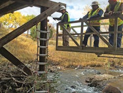
To help achieve these goals and also have the necessary equipment to support them, the UNM team employed a deployable scaffold system that allowed access to the underside of a bridge from the bridge deck itself. The scaffold required closure of one lane but could extend to a length equivalent to three vehicle lanes. So, a bridge over a highway with up to three lanes in each direction can be inspected from both sides of the bridge deck. Typical inspection time utilizing this equipment ranged three to four hours. The scaffold was able to carry the weight of a single person and his equipment; more if the arm was not fully extended.
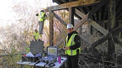
Researchers applying the sonic echo/impulse response testing method to a wood bridge pier column.
Magnetic induction method
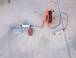
Although very limited in scope, the most reliable and inexpensive NDT method was using the Length Inductive Test Equipment (LITE) from Pile Dynamics Inc. The system relies on the changes in induced magnetic field to determine the presence of metals, and is hence useful on steel or reinforced concrete piles. When the probe section of the device is lowered into a borehole next to the pile with a plastic pipe casing (or some other nonconductive material) such as PVC (polyvinyl chloride) or PE (polyethylene), changes in the output voltage indicate the presence or absence of metal. By using the LITE system the depth and condition of the end of a metal foundation can be determined. The LITE system was used both in the lab and in the field to determine how close the sensor needed to be to detect the presence of steel; as notated in Figure 1, it consists of (1) battery, (2) signal conditioning box (constitutes the central hub of the system), (3) volt meter, and (4) probe. The probe is the sensing element and has a diameter of 1.5 in.
An experimental testbed was developed using a 12-in.-diam. concrete column embedded in the ground with three PVC pipes placed at varying distances to determine how effective and accurate the induction field method can be.
It was observed that detection is very reliable when the probe is within 1 ft of the steel or rebar, and partially reliable when 1.5 ft away. Therefore, the ability to drill in close to the pile is essential. This is often difficult due to the presence of pile caps or low clearance between the ground level and the superstructure. To address this challenge the UNM team acquired a Geoprobe (drilling equipment) that requires very limited clearance to drill close to the piles.
SE/IR method
Sonic Echo/Impulse Response (SE/IR) was found to be the best compromise between simplicity and reliability for wood and concrete foundations. A sound wave is generated, preferably at one extreme end of the pile (i.e., at the top), and the time duration of the reflected waves is used to determine the pile depth. Alternately, frequency analyses can also provide the same results, at times with greater reliability. If the reflections are weak due to decay of the sound wave, the first or second reflection is all the data available for a time-based analysis. If the reflections are good but extraneous noise sources make time-based interpretation difficult, frequency-based interpretation can provide more reliable results.
Tests were conducted in the laboratory and on several local bridges, including a railway bridge. Ideally if the top of the pile is accessible, vertical strike with the instrumented hammer creates the most reliable source of sound that reflects from the bottom, providing an indication of the pile length. If the top of the pile is inaccessible, sonic waves in the pile would be generated by striking vertically upwards to the pile cap close to the pile, or on wooden blocks screwed on to the pile. Alternately, horizontal striking directly on the side of the pile is possible, but precautions need to be taken to avoid setting the pile/bridge into vibration modes. Likewise, striking too close to the attached sensors (accelerometers or geophones) can cause them to vibrate and generate spurious signals. In addition, while a sensor is mounted somewhere far from the top of the pile, it receives different echoes at different times; reflection of the sonic waves from the top of the piles and superstructures make it more complicated. This is especially true when there is more than one sensor used in the investigation.
To alleviate such complications, test results also were being compared against numerical (Finite Element) analyses. Multiple reflections are typical in sonic tests including conversion of P (molecular motion along the direction of wave propagation) and S waves (molecular motion perpendicular to the direction of wave propagation) that travel with different velocity. Modeling of the foundation with attached superstructure provides the means to understand various reflections and to what extent they may affect the results. Interpretation of results also is affected by the duration of impact and imparted energy. A harder hammer tip and faster impact decreases the duration of impulse (the pulse is more sharp and peaks are more identifiable), but also may generate unwanted vibration in the structure. In particular, lateral striking (rather than vertical) often results in unwanted structural vibration modes interfering with the testing.
Using SE/IR tests on steel pile foundations turned out to be a difficult problem. Lateral strikes or striking vertically on a bolted steel block results in some component of the bridge vibrating and creating unwanted sources of sound and noise. Also, traffic on steel bridges does not damp out as quickly as that on concrete and wood bridges. In general, the reliable means of testing steel foundations is either the magnetic induction method or the parallel seismic method, both of which require drilling in close proximity to the steel piles. Battered piles require the drilled hole (with a PVC or PE pipe) to be at the same angle as the pile.
Figure 1. The constituents of the magnetic induction method: 1) battery; 2) signal conditioning box; 3) volt meter; and 4) probe.
Parallel seismic method
The UNM team also conducted Parallel Seismic (PS) tests. PS testing consists of lowering a sonic probe into a water-filled PVC pipe placed parallel to the foundation while a sound wave is imparted at a fixed location on the pile above ground level. As the probe is lowered, it takes longer for the sound wave to reach the probe. Once the probe is lowered beyond the bottom of the pile, the sound takes significantly longer to reach the probe since it travels a greater distance through the ground vs. through the pile. This is evident in the form of a kink in the duration of sound travel; the kink indicates the bottom of the foundation. The technique is quite reliable except when the foundation sits on hard bedrock since the wave propagation speed in the bedrock is comparable to that in the pile. Fortunately, hard bedrock is easily identified during the drilling operation and this anomaly is easily resolved, along with the fact that a pile sitting on hard bedrock is, in general, safe from scour failure.
Future work
This work was funded with a three-year research grant supervised by Dr. Thiet Nguen (FHWA), Bob Meyer (NMDOT) and Michelle Mann (NMDOT). Summer 2016 will see the research team transitioning into a service contract to inspect bridge foundations throughout the state of New Mexico. The team also is exploring the potential for providing services to other states and agencies.
About The Author: Maji is a professor of civil engineering at the University of New Mexico. Ng is a professor of civil engineering at the University of New Mexico. Rashidyan is a Ph.D. candidate in the department of civil engineering at the University of New Mexico.
