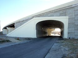
Tunneling through Indiana
An Indiana Department of Transportation Toll Road district project, involving the replacement of several miles of east and westbound highway lanes, also included total reconstruction of numerous bridges within the project's limits. One of these bridges was identified in Lake County, just east of Chicago, as a 778-ft-long multispan steel girder bridge at the junction of US 20-12 and the Indiana Toll Road.
As part of Indiana Toll Road Project 2000, the steel structure originally was scheduled to be replaced with a new widened structure of similar length. When consulting engineers RQAW Corp. performed the initial scoping and planning on the project, however, they found an alternative solution.
"During the preliminary planning stages, RQAW determined that this structure could be significantly shortened and simplified if an alternative method was used to provide access to Taylor Road, which served as an entrance to a small industrial facility," said Stanley Jones, project engineer for RQAW.
To provide access to Taylor Road, RQAW specified a CON/SPAN vehicular tunnel that would pierce the steel girder bridge abutment wall and exit through the mechanically stabilized earth (MSE) face panels.
"For appearance and ease of construction, a CON/SPAN structure was selected, and the proposed pile cap used at this abutment was designed to span over the width of the CON/SPAN," Jones said.
CONTECH Bridge Solutions provided technical support to Ken Herceg & Associates, who were called in to assist with final design. The abutment and tunnel were originally to be constructed when Toll Road traffic had been routed to the south mainland bridge. After the project was awarded to contractor Reith-Riley, however, the toll road requested that the project be redesigned to keep three lanes of toll road traffic open at all times. The proposal required one eastbound lane and one westbound lane remain open and an alternating lane that would change during morning and evening rush hours.
"The savings over the initially proposed bridge more than offset the cost of the CON/SPAN structure, and the appearance of the final product was very impressive," Jones said.
After the new lane opened, the old structure was demolished and the remainder of the tunnel was set and backfilled. The new vehicular tunnel is 119 ft long, with a 32-ft span and an 11-ft rise. The structure was placed on 9-ft-7-in. tall pedestal walls and one end is skewed 5 degrees.
