By: Gregory Stiles, P.E.; Contributing Author
The Kentucky Transportation Cabinet (KYTC) is improving the U.S. 68/S.R. 80 corridor across western Kentucky, including replacement of the obsolete 83-year-old structure over Kentucky Lake.
The new structure will provide improved safety for motorists and for commercial vessels navigating the Tennessee River inland waterway.
The construction contract for the Kentucky Lake Bridge was let on Dec. 20, 2013, and subsequently awarded to Johnson Bros. Corp., a Southland Co. (Johnson Bros.) for $131.5 million, including final roadway paving on the causeways and demolition of the old structure.
Mike McGregor is KYTC’s District 1 chief engineer and led the project through preconstruction and design development.
“KYTC’s investment will provide benefits of improved mobility for community, commerce and tourism as well as providing a reliable earthquake evacuation route for the western Kentucky region,” McGregor said about the project.
An unwritten goal
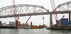
The new crossing of Kentucky Lake will be 3,611 ft long and have three units: the 1,409-ft-long four-span west approach, the 550-ft-long steel tied-arch main span and the 1,652-ft-long five-span east approach. The 75-ft-wide bridge deck will carry two lanes of traffic in each direction and a barrier-separated 10-ft-wide multi-use path on the south side.
The primary members of the main arch span floor system are 5- to 6-ft-deep transverse floor beams that are bolted to the tie girders every 45 ft. Both the floor beams and the longitudinal stringers act compositely with the concrete bridge deck, eliminating stringer bearings.
“The unwritten design goal was to make the bridge as maintenance-free and accessible for inspection as possible,” said Dennis Baron, bridge technical manager in Michael Baker International’s Louisville office. “Both the arch rib and floor beam were designed intentionally as open members rather than box sections, and welding was minimized.”
Corrosion protection is assured by specification of painted weathering steel. Baron’s son, Michael Baron, who also works for Michael Baker International in Louisville, led the coordination with KYTC’s Bridge Preservation Office to identify appropriate locations for inspector safety cable and steps built into the structure to satisfy KYTC’s policy of 100% climbing access for inspection, thus conserving future maintenance dollars.
Multiple offices of Michael Baker International worked concurrently on the design to achieve the aggressive letting schedule.
“It was a real team effort,” said the elder Baron, who mentored many younger professionals through the design effort by sharing his 50-plus years of experience in bridge engineering. “The expertise of many different bridge professionals contributed significantly to the quality of design drawings.”
The tie girders are parallelogram-shaped with 5-ft-deep flange plates bolted by sub-flanges to the 4-ft-wide webs and achieve internal redundancy by plate sizing that would carry the load with just three of the four primary plates.
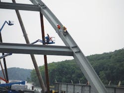
The arch ribs spring up from the knuckles and are inclined inward 15° from vertical to create the signature “basket-handle” form. Networked wire rope hangers will support the tie girders at each floor beam and also serve to brace the H-shaped ribs longitudinally.
In comparison to the deep-welded steel plate girders of the approach spans, the shallow depth of the main span’s tie girder will define the navigation channel’s improved vertical clearance, while the massive waterline pile caps guard the piers from barge impact and frame the horizontal opening for commercial vessels.
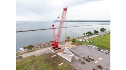
An advanced contract had extended the causeways from both shores and constructed a minor bridge over a lagoon on the western approach, providing Johnson Bros. with full marine access to the site for its crane and material barges. A full-scale pile-driving demonstration and load test program also were performed as a component of this advanced construction package.
Given the soil parameters and the site’s proximity to the New Madrid fault, the bridge was designed for AASHTO Seismic Design Category D provisions. As Darrin Beckett, of KYTC’s Geotechnical Branch, and Terracon, the project’s geotechnical design consultant, were interpreting the data from the load tests, the bridge design team of Michael Baker International for the main span and subconsultant Palmer Engineering for the approach spans continued forward with the seismic time-history analysis and preparation of final contract documents.
To keep the project on the 2013 letting schedule, the Michael Baker/Palmer Engineering team enveloped the bridge design to meet AASHTO code requirements for both 1.5-in.-thick and 2-in.-thick pipe piles. With approximately 70 ft of unsupported pile length, the resulting variation in pile stiffness significantly influenced the lateral behavior and seismic response of the structure. The final geotechnical recommendations confirmed the need for 2-in.-thick pipes, a decision made in large part to avoid damage while installing the piles through the denser layers of sand and gravel with bedded chert formations.
Beckett has overseen various phases of the geotechnical engineering work on this project throughout most of his career, from preliminary design through construction.
The shallow depth of the main span’s tie girders will aid the navigation channel’s improved vertical clearance.
“It has been personally fulfilling to be involved in such a unique and challenging project. We have learned a great deal of information from our load test program that will tremendously benefit both geotechnical researchers and practicing engineers,” said Beckett.
Steel pipe piles were fabricated by Greens Bayou in Houston, Texas. Each main span pier of the bridge is founded on 14 steel pipe piles 6 ft in diameter with 2-in.-thick pipe walls. The longest piles on the project were furnished 199 ft in length at the main span piers, where the water is typically 65 to 70 ft deep between the former river banks. An additional 20 ft of furnished length was specified for test piles of main piers 4 and 5 to allow for multiple restrikes as part of the process to establish production-driving criteria.
Along with hardened steel-driving shoes, an internal constrictor plate assembly was fabricated as a grillage and washer-shaped round plate to form a soil plug within the open-end pipe pile, providing end-bearing resistance in addition to the skin friction developed with driving.
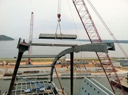
Arch Structural Steel was fabricated by Veritas Steel at its plant in Eau Claire, Wis. Collaboration between owner, contractor, fabricator and engineer began early in the contract. As the mill order deadline drew near for the HPS70W plate steel from Nucor, Veritas Steel’s Project Manager Jay Stendahl requested revising the number of tie girder splice locations from 8 to 12, thereby dividing the 526 ft between knuckles into segments all less than 50 ft in length. Michael Baker International evaluated the internal forces at each new splice location and provided the information with appropriate splice plate and bolt pattern. Associated minor adjustments to internal diaphragms were detailed and approved through the shop drawing submittal and review process.
Walter Gatti of Tensor contributed his experience to benefit the project during several collaborative teleconferences hosted by the contractor. Tensor produced 281 shop drawings, including cambered geometry diagrams, framing plans, cutting diagrams, shop-assembly diagrams and shop drawings for the tie girders, floor beams, stringers, ribs and bolted connections.
Ryan Gossom, KYTC’s construction liaison to the project, visited all the fabrication plants at the kickoff of shop fabrication and also visited on subsequent occasions to coordinate with KYTC’s inspection consultant, Bureau Veritas, for shop inspection of quality control and welding procedures.
The knuckles were the most complex pieces fabricated. Each knuckle was built of over 60 separate pieces of M70-HPS70W and M70-50W plates, angles and channels and connected with over 500 A325 high-strength bolts of 1 in. and 1¼ in. diameter. The knuckle has the inclined parallelogram shape to match up with the tie girders. Multiple diaphragms distribute and transfer loads from forces entering the knuckle at the jacking diaphragm, bearing diaphragm, end floor-beam diaphragm, forward-bearing diaphragm and rib diaphragm.
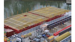
Johnson Bros.’ Project Manager Mike Brown and Project Engineer Brandon Stidham directed the many concurrent tasks in the field. The main span piers were formed by placing precast soffit slabs between piles, adjusting them with diver assistance, and then flying in by crane the bullnose plate girder forms in two segments. Once the seal concrete had been placed using a tremie, Johnson Bros. had effectively created floating cofferdams and dewatered to allow rodbusters access for rebar placement.
“Our barge-mounted ringer cranes maximized the efficiency in which the main span piers could be built considering the size, weight and complexity of design” said Brown. “The challenge was rewarding for Johnson Bros. and our team to provide a quality product of this magnitude in a tough marine environment.”
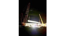
Workers monitor the placement of arch ties.
Tie girder splice locations were placed every 50 ft on the arches.
A construction joint was requested and permitted one-third of the way up the footing, effecting a two-stage placement. Once the 4-ft lower placement had cured, the primary reinforcing steel for the 13-ft-diam. pier columns was placed on it. The upper footings required over 1,800 cu yd of Class A concrete, delivered by a continuous convoy of concrete trucks from Federal Materials onto the existing bridge. From positions on the water flanking the 138-ft by 42-ft pier footings, ringer cranes swung buckets up to beside the old truss to receive the discharge from concrete trucks and then swung them back to waiting placement crews. Pier 5 took over 32 hours to place, while Pier 4 took 29 hours.
Mass concrete provisions were satisfied using cooling pipes to circulate lake water throughout the footing to regulate the core temperature, while insulating blankets kept the differential temperatures between core and surface within tolerance.
Sibling beauty
Many dedicated professionals contributed to the fabrication and on-site construction effort for the Kentucky Lake Bridge Project. With the sister bridge now also under construction on Lake Barkley, just 8 miles away, these signature basket-handle tied arches known as the “Lake Bridges” will soon stand proudly for future generations as modern gateways for visitors and locals alike entering the land between the Lakes National Recreation Area.
Mike Oliver, section engineer for the Murray Section in KYTC District 1, recognized the accomplishment with these words: “I am extremely proud of the work that has taken place thus far on the Lakes Project. The cooperation and teamwork between everyone involved has made this all possible, including the contractors, design team and inspection crew. I’m particularly proud of Bryan Black, the KYTC resident engineer on Kentucky Lake, who has played a crucial role in the success of this project. The completion of these two bridges will not only be a beautiful addition to the western Kentucky skyline, but also will be a cornerstone of the transportation infrastructure.” R&B
About The Author: Stiles is the design engineer of record for the main span of the Kentucky Lake Bridge.
