Looped in
Connected vehicle (CV) applications present new solutions to many traffic engineering problems; however, real-world testing of some of these applications is not safe and cost-effective. CV applications thus use traffic simulation software for evaluation and testing. Even though simulation models are a great tool for evaluating different traffic solutions, they might lack realism. Hardware-in-the-loop (HITL) overcomes these shortcomings. It allows traffic simulation software to interact with real-world signal controllers and real vehicles using DSRC radios.
Researchers have extensively used HITL platforms to evaluate traffic operation strategies such as transit priority, adaptive signal control, intersection operations for oversaturated conditions and truck safety systems. Previous research has used an HITL system to evaluate intelligent bus priority strategies at traffic signals and simulated diamond interchanges using HITL. These studies found that HITL provides a more realistic representation of the signal controller, and therefore that HITL can have a wide range of applications.
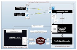
A Hardware Testing Environment (HTE) enables users to test CV application in a controlled field setting. The HTE consists of hardware components, software modules and related interfaces. HTE provides a controlled environment to test CV components such as roadside units (RSUs), on-board units (OBUs), Dedicated Short Range Communication (DSRC), and SAE J2735 messages including the MSG_SignalPhaseAndTiming Message (SPaT), the MSG_MapData (MAP), and the MSG_BasicSafetyMessage (BSM). The HTE is capable of supporting other SAE J2735 messages as well. The following sections describe the various HTE software and hardware components and their interfaces. Figure 1 illustrates the various components of the HTE and the interfaces between them.
Figure 1. The Hardware Testing Enviroment, which enables controlled CV field testing.
Traffic simulation environment
The traffic simulation environment (TSE) consists of a microsimulation software called VISSIM. It simulates detectors and connected and regular vehicles. VISSIM provides detector status information (detector calls) to enable the traffic-signal controller (TSC) to run in actuated mode. TSE also simulates the real vehicle driving at the intersection by using the trajectory information from BSMs. This environment consists of several interfaces that enable:
- Extraction and communication of simulated vehicle information with RSUs and OBUs;
- VISSIM to receive BSMs from real vehicles;
- VISSIM to receive signal timing and phase status from the traffic-control devices present at the test intersection; and
- VISSIM’s driving simulator API to simulate vehicle movement of the real vehicle using the BSMs.
The TSC-HITL software module is an interface between VISSIM and the external TSC. The objective of this module is to enable TSE and the TSC to share data so that the external TSC can control traffic at both real and simulated intersections within VISSIM. The module takes the simulated vehicles detector actuations and places detector calls on the corresponding detectors in the real TSC. The module also provides VISSIM with the status of all active phases in the TSC. Consequently, real CVs driving at the intersection and simulated vehicles within VISSIM will have the same phase status at any given time.
The Vehicle to Infrastructure (V2I) Hub facilitates development and testing of infrastructure applications in a CV environment. The V2I Hub consists of core modules that facilitate the generation of SAE J2735 messages, i.e., broadcast of these messages to equipped vehicles (infrastructure to vehicle [I2V]) via DSRC RSU, and reception of messages broadcast by equipped vehicles. Researchers added a new plugin called the VISSIM plugin to the V2I Hub core suite of plugins. The VISSIM Plugin generates BSMs for the simulated vehicles in VISSIM and broadcasts them to CVs at the intersection via the RSU. Before broadcasting the BSM to the V2I HUB, the TSE coverts local x-y coordinates of VISSIM to latitude and longitude coordinates using a reference point. A reference point is a point whose x-y coordinate in VISSIM and latitude and longitude on the world map are known. The researchers used a flat-earth approximation to transform the x-y coordinates of VISSIM simulation vehicles into latitudes and longitudes. The plugin also sends the location of the real CV (latitude and longitude) driving at the intersection to VISSIM. The plugin then converts the latitudes and longitudes to local x-y coordinates of VISSIM using the same reference point.
The SPaT plugin receives the SPaT data from the real TSC at the intersection, generates the SPaT message, and broadcasts the message to CVs driving at the intersection via the RSU 10 times per second. The MAP plugin generates and broadcasts the geometric information of the intersection, i.e., the available lanes and movements from each lane, to CVs at the intersection once per second.
Researchers installed an Econolite ASC-3-2100 SPaT-enabled controller at the test intersection. The TSC is capable of generating SPaT data 10 times per second over a UDP socket to the V2I Hub using NTCIP protocol. The SPaT plugin on the V2I Hub uses the SPaT data to generate the SAE J2735 SPaT message and broadcast it to the real vehicle driving at the controlled intersection environment via a DSRC RSU. Besides controlling the traffic at the controlled intersection environment, the TSC also controls the traffic within VISSIM simulation.
An Arada Commando (Arada is currently known as Lear) RSU is used in the HITL to broadcast and receive SAE J2735 messages, i.e., I2V and V2I Hub communication, between the infrastructure and the CV driving at the controlled intersection environment. The roadside V2I Hub interfaces with the Arada RSU to broadcast infrastructure messages including the SPaT and MAP messages to the real vehicle driving at the intersection. It receives the BSMs broadcast by the real vehicle at the roadside and passes it to the V2I Hub. In order to facilitate the creation of the augmented environment at the controlled intersection where the real vehicle can see and interact with simulated vehicles, the RSU also broadcasts BSMs of the simulated vehicles to the real vehicle driving at the intersection.
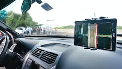
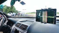
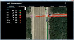
The researchers installed the Arada Mini 2 OBU in the real vehicle driving at the controlled intersection environment. The OBU broadcasts BSMs of the real vehicle that include its location, speed and heading 10 times per second. The Arada Mini2 OBU also receives the SPaT and MAP messages broadcast by the infrastructure. The Arada OBU in the real vehicle also receives the BSMs of the simulated vehicles broadcast by the infrastructure as if they are real vehicles broadcasting their BSMs. The Arada OBU pairs with a Samsung tablet in the real vehicle using Bluetooth. The OBU forwards all the messages it receives from the infrastructure (SPaT, MAP and BSMs of simulated vehicles) to a mobile application on the tablet. The tablet displays the intersection lanes, movements available in each lane, movement status (green, yellow, red) and location of simulated vehicles at the intersection in addition to the location of the real vehicle to the driver in the real vehicle.
Figure 2. HITL infrastructure equipment layout.
HITL implementation
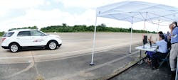
Once all the components of the HITL were developed and configured, researchers implemented the system at the RELLIS Campus of Texas A&M University. The implementation included an Econolite TSC in a TS-2 cabinet. The cabinet also housed a V2I Hub. The V2I Hub interfaced with the signal controller, the Arada RSU and a laptop running the VISSIM simulation model as illustrated in Figure 2. The research team instrumented a TTI vehicle with an Arada OBU and a Samsung display as illustrated on pages 4 and 5.
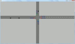
Figure 3 illustrates the display in VISSIM simulation and the tablet display when HITL simulation is running in a single figure to show the synchronous nature of these simulations. The left display is for tablet and the right one is for VISSIM. The blue vehicle in both tablet and VISSIM windows is the real vehicle with an OBU. In the tablet display, a lane is marked green if that approach has a green signal and is marked red if that approach has a red signal. The tablet application illustrates the VISSIM vehicle as magenta-colored vehicles. In the VISSIM screen, the black-colored vehicles are the VISSIM vehicles.
Figure 3. VISSIM and tablet display during HITL.
Conclusion
The research team illustrated the development of an HITL platform that enables users to simulate CV by using a VISSIM microscopic simulation model, an external TSC, an actual CV, DSRC radio, and an RSU. The TSC receives detector status from VISSIM and sends out a phase status. This paper explains the various components of this HITL platform and explains the interactions between them. The HITL platform developed in this study provides the capability of testing various CV applications in a safe and cost-effective manner. FHWA is working on evaluating cooperative adaptive cruise control using this platform. Future studies can look into testing CV applications such as red light violation warning or forward collision warning systems.
Acknowledgments: This work was funded by the FHWA’s Exploratory Advanced Research Program. The research team appreciates the support of Peter Huang from Turner Fairbank Highway Research Center for providing support and guidance for the successful completion of this project and subsequent demonstrations to multiple panels.
