A rise at the Falls
Just to the north of roaring Niagara Falls is the heavily traveled Lewiston-Queenston bridge connecting New York State to Ontario, Canada, over the mighty Niagara River.
The I-190 corridor that serves the bridge traverses a multitude of critical infrastructure, which supplies nearly 5 million New Yorkers with electricity.
It is no wonder that rehabilitating the I-190 and S.R. 265 bridges over the New York Power Authority (NYPA) Powerplant Forebay required innovative approaches to a number of challenges. This $41.8 million New York State Department of Transportation (NYSDOT) design-build bridge rehabilitation project included the staged superstructure replacement of three adjacent 816-ft-long bridges. The project was completed in two construction seasons and was opened to traffic in the fall of 2015.
The bridges’ primary fault was deterioration of the post-tensioned concrete I-beams after initial bridge inspections revealed several areas of deterioration. These included concrete spalling, exposed and broken post-tensioning tendons, exposed reinforcement, and corrosion and section loss on the post-tensioning anchorages at the beam ends. The project featured the complex removal of the existing 12-span post-tensioned concrete I-girder superstructure for each bridge and its replacement with three sets of four-span continuous, galvanized steel, multi-girder superstructures. Also required was the relocation of numerous utilities—proving to be yet another challenging aspect of the project.
Complex generating
The I-190 northbound and southbound and S.R. 265 (Military Road) bridges were built in 1960 as part of the Lewiston Pump-Generating Plant, located near Niagara Falls, N.Y. They are owned by the NYPA. The three adjacent bridges had a combined width of 131 ft and were separated by a mere 2 in. Each superstructure was comprised of 12 simple spans of post-tensioned concrete I-beams with an 81⁄2-in. composite deck spanning 68 ft from center to center of the piers. The substructures are reinforced concrete and are continuous below each bridge. The piers are 6 ft wide and approximately 95 ft tall, and are in contact with the pump-generating plant to the east.
This bridge rehabilitation project had many challenges due to the numerous utilities that had to be maintained, the deteriorated condition of the post-tensioned bridge girders and access limitations imposed by NYPA. Some of the project highlights and details are enumerated as follows:
Keeping the traffic flowing
Replacement of the superstructures was completed in three stages each, maintaining two lanes of I-190 northbound traffic, and one lane of I-190 southbound traffic at all times while providing for a construction work zone on the bridges. The parallel S.R. 265 (Military Road) traffic was detoured off-site for the entire project duration. Due to NYPA security restrictions, access from the forebay water below the bridge was not permitted and therefore all construction activities were performed from either the existing or newly constructed superstructures.
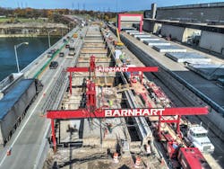
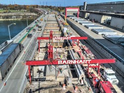
Custom gantry crane removing beams in I-190 NB Bridge.
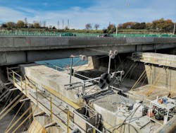
Pre-engineered platform/containment system
During demolition and reconstruction activities, it was imperative that no concrete or debris were dropped below the bridges to prevent damage to the NYPA turbines and pump intakes located below the bridge. To meet this requirement, a pre-engineered, prefabricated, modular QuikDeck system for debris containment was installed below the entire bridge, which also served as an access platform for the work. The platform was supported via diagonal suspender chains anchored to the piers, an innovative method first used on this project. This system provided 100% coverage below all three bridges and saved time in the project schedule over conventionally constructed work platforms. The installation of this system was done from the existing bridge, and it did not require any work from the water below; this would have been problematic due to the turbine intakes below each bridge span.
Mobile gantry crane
A mobile gantry crane—custom designed and built by Barnhart Crane and Rigging Inc.—was used to increase production and minimize stresses in the existing and proposed structures during the demolition of the existing bridges. The crane was designed and tested for a maximum lift capacity of 76 tons with the maximum weight of the heaviest beam with bonded deck estimated at 67 tons. To ensure that the capacity of the crane was not exceeded, in case a beam was hung up for instance, load cells were attached to the rigging of the crane to monitor the loads while they were lifting. The crane was used to lift out the existing concrete I-beams (with a portion of the deck), waterline support bridges and existing utilities portions of the deck during demolitions. The gantry crane spanned from pier to pier, extended over into the adjacent bridge work area, and was supported by a combination of columns and a multi-axle trailer, which was blocked to the top of the deck surface when in the final position. The columns were supported on the existing pier tops at the trailing end of the span and on the existing deck/beam ends at the leading end of the span. Multi-axle trailers (a Goldhofer transport system with tractor) supporting one side of the mobile gantry crane allowed the entire crane to be easily moved to successive spans. Using this system, stresses in the existing beams under the demolition equipment were kept below an HS 20 equivalent loading.
I-beams were removed with a portion of the deck and sometimes with the concrete bridge barrier attached. For this project, engineers developed detailed drawings showing where the deck was to be cut to keep the beam/deck weights below the crane capacity and also account for load eccentricities while lifting the beams. The deck was cut almost entirely ahead of the crane picks, leaving only short sections of deck to be cut with the diamond saws after the crane was rigged to the section being removed. The pre-cutting of the deck allowed the beam/deck sections to be removed more quickly because only a small amount of cutting was necessary to release the section being lifted.
The removed sections of the bridge superstructure were loaded onto a transport trailer and taken to a processing yard on the project site for crushing, removal of reinforcing steel and subsequent recycling of both the steel and concrete. Since there were a number of beams on the bridges that had broken post-tensioning strands—reducing their capacity—a path was shown on the drawings for the transport drivers to follow a prescribed path to avoid the damaged beams.
Utilities
Numerous utilities and utility vaults were embedded in the concrete deck of these bridges. Maintaining the functionality of these utilities during construction proved to be a challenge, with only short outage periods for tie-ins. The utilities included two 24-in. water mains, an 8-in. natural gas line, 34.5-kV and 4.8-kV electric cables, two fiber optic cables, telephone cables, television cables and roadway lighting cable. To maintain the integrity of these systems, the infrastructure had to be constructed in a new location before the existing utility could be removed. The staging of this work and the tie-ins required seamless coordination with the utility owners, and was nearly as time-consuming as the bridge superstructure replacement itself.
Wire sawing of concrete
The tops of all 11 concrete pier stems were cut off at a specified elevation, using wire sawing equipment so they could be removed in large sections with a rough terrain hydraulic crane. Each pier stem was cut into blocks and then slid across the remaining stem with a tracked excavator to move the block within the pick capacity of the crane. The concrete slurry remaining after the wire sawing served as a lubricant to facilitate this sliding. Using the wire sawing equipment provided a level concrete surface to dowel in reinforcing steel for the reconstruction of the pier tops. Additional local removals were done with this equipment to allow the new waterlines to pass through the pier stems while providing the required clearance to the superstructure.
The deck slab and the concrete diaphragms between the concrete I-beams also were cut into manageable sections by wire sawing, along with walk-behind saws, before being lifted out by the mobile gantry crane. Utilizing these concrete removal methods minimized vibrations transmitted to the adjacent NYPA power facility—as compared to the usual concrete breaking methods—and avoided the potential for concrete debris dropping into the power-plant forebay.
Wire sawing on the I-190 NB Pier Top, with the new I-190 SB Bridge in the background.
Specified replacement concrete
All materials used on this project had to meet the requirements contained in NYSDOT’s Standard Specifications as identified in the contract documents. The primary concrete mix designs used were high-performance concrete (HP) for the bridge deck and pier modifications, self-compacting concrete (SCC) for pier repairs and Class J concrete for the slip forming of the concrete bridge and approach barriers. The mix designs used exceeded the compressive strengths in all tests. All mixes included fly ash to improve the properties of the concrete. The addition of fly ash to all three mixes increased the compressive strength, reduced the permeability and improved the durability of the hardened concrete. In addition, it improved workability and reduced the heat of hydration in the fresh concrete. Conservatively, the engineers used 3,000 psi for design, even though the compressive strengths obtained were higher.
Anodes in repair areas
The top 2-ft section of all 11 piers was replaced to accommodate the new superstructure; this had the added benefit of removing the most chloride-contaminated portion of the pier caused by roadway joint leakage. The portion of the piers between the waterline and the new concrete had some minor deterioration which also was addressed during the project. These repairs were generally shallow, amounting to less than 8 in. in depth. Contract plans required that all repairs had to go a minimum of 1.5 in. behind the reinforcing steel so that they were embedded in the repair. Additionally, they were dovetailed around all edges of the repair. When completed, the concrete in the repaired areas was anchored by the reinforcing steel and was “locked in” by the dovetail detail. Galvanic anode devices were attached to the exposed reinforcing steel in the repair areas to combat the anode ring effect that occurs when placing fresh concrete adjacent to the existing salt-contaminated concrete.
Done in two
Rehabilitating the I-190 and S.R. 265 bridges over the NYPA Powerplant Forebay required innovative approaches due to a unique project environment. From maintaining traffic flow and utility functionality to pre-engineering an altogether new method of mitigating debris interference with a major hydropower facility to incorporating concrete blends that surpassed the NYSDOT’s Standard Specifications, this project’s success was characterized by creative approaches to unique problems. Groundbreaking construction methodologies and superlative attention to detail also were themes throughout the course of the project, which despite all constraints was completed in just two construction seasons.


