By: Mike Perez, P.E., and Wade Bonzon, P.E.
The fast-growing city of Houston, Texas, will soon see construction begin on a world-class cable-stayed bridge intended to relieve congestion and improve safety on one of the busiest toll road networks in the country.
Located on the eastern side of the city, this new signature bridge will replace a previous record-setting concrete segmental bridge as the Harris County Toll Road Authority (HCTRA) widens the Sam Houston Tollway (SHT) East where it crosses the Houston Ship Channel.
One-fifth of the way there
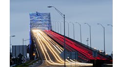
The SHT is one of only five available means of crossing the Houston Ship Channel. It has experienced significant increases in traffic over the last several years, and traffic demands are expected to grow from 54,000 vehicles per day in 2013 to almost 158,000 vehicles per day by 2035. Where it crosses the channel, the existing SHT is offset to the east side of a 200-ft-wide right-of-way and is surrounded by industrial facilities. When the existing bridge was constructed, it was envisioned that a twin span might someday be needed to upgrade traffic capacity on the tollway. However, the existing bridge, with only two lanes of traffic in each direction with no shoulders, was too narrow to satisfy future traffic needs.
To accomplish the SHT widening within the existing right-of-way while maintaining all four existing lanes of traffic throughout construction, the project team developed a phased construction sequence. First, a new four-lane southbound bridge would be constructed directly adjacent to the existing bridge. Traffic would then be switched to the first new bridge in a temporary bi-directional configuration while the existing bridge is demolished. The new northbound bridge would then be constructed along the alignment of the existing bridge. One final traffic switch would then allow each new structure to carry four lanes of traffic with full shoulders.
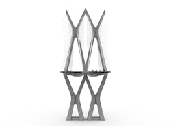
The selected pylon shape on the Ship Channel Bridge has inclined legs similar to conventional A-frame or diamond-shaped cable-stayed bridge towers.
Going long
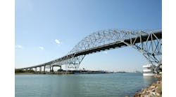
The Port of Houston has been working to widen and deepen the navigation channel for several years. The existing bridge over the Houston Ship Channel is a cast-in-place segmental box girder structure with a main span of 750 ft. Although the longest span of its kind in the U.S. when it was built, even at that span length the main piers are located within the waterway and are a potential impediment to channel traffic and would likely need to be retrofitted with enhanced protective measures when the Port of Houston widens the channel at that location.
Therefore, structures with longer span lengths needed to be considered. The project team recognized that spanning the channel completely would simplify the permitting process and result in cost savings by avoiding foundation construction within the waterway. This option also eliminated the need for ship impact protection structures and allowed unfettered future navigation-channel widening by the U.S. Army Corp of Engineers.
Placing the main pylon foundations outside of the waterway required a main span length of more than 1,300 ft. Given the magnitude of the new bridge structure, HCTRA recognized the need for a durable structure type that would minimize costs to maintain it during its service life in the humid coastal climate near the Gulf of Mexico. For this reason, steel bridge options including box girder, tied arch and cable-stayed types were not advanced into the final structure-type selection process in favor of structure types using prestressed concrete. At that span length, a cable-stayed bridge became the optimal structure type for the area’s poor soil conditions and best served HCTRA’s desire for a low-maintenance structure.
With a main span length of 1,320 ft and pylons more than 500 ft tall, the proposed bridge is spectacular in its sheer size and scale. However, because most of the area below the bridge is inaccessible to the public, HCTRA wanted the aesthetic design efforts to focus on providing drivers with a unique visual experience as they cross the bridge. Thus, pylon shapes and the associated stay-cable geometries that accomplished this goal were considered. The selected pylon shape has inclined legs similar to conventional A-frame or diamond-shaped cable-stayed bridge towers. However, the legs form an X-shaped configuration above deck level. The result is a dynamic experience for drivers as they pass under the varying angles of each stay cable. The selected geometry also provides a rigid frame structure that can be constructed in stages while efficiently resisting the high winds frequently seen in the Texas coastal region.
The selected box girder superstructure cross-section further enhances the elegant and slender appearance of the bridge while providing a durable and constructible superstructure with excellent stability in high winds. The superstructure box girders are framed integrally into the main pylon diaphragms to eliminate the need for large bearings at the pylons and provide overturning moment resistance during cantilever erection. The resulting connection further reduces visual bulk and creates an efficient and slender bridge structure.
The final proposed main span configuration consists of twin five-span cable-stayed concrete box girder bridges, each carrying four lanes of traffic with full 10-ft shoulders. The box girders have a constant overall depth of 12 ft 1 in. The span layout is symmetrical with back spans of 240 ft and 460 ft, separated by an interior pier. The main span length over the ship channel is 1,320 ft. The four planes of 16 cables at each pylon anchor along the edges of the box girders at a typical longitudinal spacing of 37 ft 4 in., although the superstructure box girders carrying the northbound and southbound SHT roadways are generally separate, with the two bridges being connected only at the main pylons.
To minimize cracking and maximize long-term durability, the box girders are post-tensioned in two directions. A series of internal and external top- and bottom-slab tendons control erection and live-load stresses in the longitudinal direction. Transversely, four-strand tendons run through the deck and anchor at each wingtip. In addition, four-strand tendons run through the webs and bottom slab to control transverse tensile stresses in the permanent condition. Diagonal struts support the top slab, shortening its transverse spanning distance and stiffening the box girder cross-section. The shallow sloped webs connect the thickened edge beam directly to the bottom slab.
Placing the main pylon foundations outside of the waterway required a main span length of more than 1,300 ft; the pylons reach over 500 ft tall.
“Pipeline Alley”
The historical Boggy Bayou underlies the project alignment on the south side of the ship channel but has since been filled by dredge spoils and other earthmoving activities, resulting in very poor soil conditions near the surface. Below the fill zone the soil profiles consist of cohesive clays throughout the area of the project with some sand lenses of varying thickness at depths of 60-100 ft. No bedrock was encountered, even during borings extending to depths of more than 400 ft. Potential long-term consolidation of the clay layers under load became an important design consideration.
The area surrounding the SHT alignment has undergone significant industrial development. A major transfer facility operated by the Kinder-Morgan corporation now surrounds the bridge alignment south of the channel. That facility features rail tracks, conveyor structures and pipelines near the existing and proposed bridges. More than 90 buried and exposed pipelines and other utilities cross the tollway alignment near the south abutment in an easement so crowded that the project team referred to the area as “Pipeline Alley.” The phased construction scheme for the proposed bridge resulted in the need to build many foundations very close to the existing bridge substructures. Driven piles were considered but were ruled out in favor of drilled-shaft foundations for their ability to provide relatively compact foundation footprints, a reduction in the overall number of construction operations, and minimize potential effects on surrounding structures and stakeholders from vibrations and noise.
Parametric studies of the main pylon drilled shafts found that the optimal drilled shaft depth, spacing and layout could be provided with a rectangular pattern of 48 ~ 8-in.-diam. shafts. An arrangement of 4-in.-diam. drilled shafts was used for the back-span piers, which carry far less load than the pylons. The selected main span bridge shaft diameters also were used for many of the approach bridge foundations.
FEM analyses performed during the geotechnical study identified the potential for as much as 10 in. of combined short- and long-term consolidation of the clay layers at the pylon foundations. Based on these predicted movements, several foundation settlement load cases were included in the main span bridge design.
The beam and the winch
Cable-stayed bridges of this span length are typically erected in balanced-cantilever to limit falsework needs. Bridges with box girder cross-sections can be erected in segments either cast-in-place with self-launching form travelers or precast and then lifted into place at the cantilever tips. Both options were considered for this project.
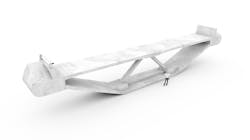
The proposed erection scheme uses simple beam-and-winch systems to lift the precast segments into position at the ends of the cantilevers. Equipment like this is relatively inexpensive and has been commonly used on similar projects around the U.S. Because beam and winches lift segments straight upward, all segment erection can be accomplished without swinging loads outside of the narrow HCTRA right-of-way. In the proposed erection scheme, segments are delivered to the main span cantilevers directly via barges. Back-span segments are delivered to the pylon footing, which doubles as a loading dock, and then transported into position below the beam and winch using segment haulers.
The selected box girder superstructure cross-section further enhances the elegant and slender appearance of the bridge while providing a durable and constructible superstructure with excellent stability in high winds.
Stays ahead of the game
The cable system designed for the new Ship Channel Bridge represents the state-of-the-art in cable-stayed bridge technology. It incorporates features that maximize the service life of the system through enhanced corrosion protection, and reduces the cost and complexity of future cable maintenance.
The bridge has 128 separate stay cables comprised of coated 0.6-in.-diam. seven-wire strands. The cables vary in size from 43 to 75 strands, and each stay cable includes two reference strands that can be removed from the bridge by HCTRA at any time during its service life to allow physical inspection to verify the strand condition.
FIGG’s Stay Cradle system is used to efficiently transfer stay cable forces via compression into the pylon concrete, eliminating the need for complex and expensive steel anchorage boxes to resist the large tension stress field between pylon anchorages. This simplifies the design, and detailing of the pylon legs allows for the use of less material in the design of the pylon itself. The Stay Cradle eliminates the need to access the upper pylon during any future stay strand removal or replacement operation. The entire stay system is designed to allow full replacement of a stay’s strands by only accessing the deck-level anchorages. This reduces lane closures and their associated traffic maintenance and protection costs because deck-mounted equipment is not needed to access the upper pylon. It minimizes impacts to toll revenues even during replacement of the key load-carrying members of the structure.
The stay strands are protected by an outer sheathing pipe made of thick-walled high-density polyethylene (HDPE). Unlike many cable-stayed bridges, the Ship Channel Bridge’s stay system is designed with gas-tight connections in the outer sheathing, further protecting the strands and anchorage areas from moisture and condensation resulting from ambient humidity variations in the surrounding coastal environment. The gas-tight design of the exterior sheathing allows enhanced corrosion protection by replacing the atmospheric air in the stays with 99% nitrogen gas. This prevents ambient oxygen from initiating corrosion of any critical load-bearing stay elements. Pressure monitoring will be provided at each stay cable so that inspection crews can continuously verify system integrity. This also reduces the need for costly visual inspection of the stay-cable exteriors which can disrupt traffic with deck-mounted equipment. The inert gas-corrosion protection eliminates the need for wax in the stay-cable anchorage zones, further simplifying removal of reference strands or replacement of structural strands, and allowing direct visual inspection of the strand and anchor wedges at the face of the anchorage block through a transparent window in the stay-anchor caps.
The 4-mile-long program corridor will be constructed in three design-bid-build construction projects with a combined estimated construction cost of just under $1 billion and a construction duration of 6-½ years. The first contract, which includes the cable-stayed main span bridge, is the largest single contract ever advertised by Harris County. Final design of the new bridge was completed in March 2017, and evaluation of contractor proposals is underway. Notice to Proceed for the successful contractor was expected by the end of 2017. The new southbound bridge will be opened to temporary bi-directional traffic in early 2021. Overall project completion, including demolition of the existing bridge and the construction of the new northbound bridge will be completed by mid-2024.
About The Author: Perez is a senior staff engineer with the Harris County Toll Road Authority, Houston. Bonzon is regional director for FIGG Bridge Engineers, Dallas, Texas.


