By: Buckley Williams and Kent Ponder, P.E.
The design and construction industry is constantly seeking project delivery methods that foster better communication and collaboration among team members.
While these innovations can surely help the industry as it moves into the future, teams in so-called traditionally delivered projects can still exhibit high levels of cooperation, resulting in substantial benefits to the project.
A $31 million bridge-widening project in Orange Park, Fla., is one example.
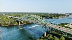
The Doctors Inlet Bridge was built in the 1960s to replace an old concrete and steel bridge with a swing span. It consists of twin two-lane spans that connect six-lane highways to the north and south along U.S. 17. The spans over the inlet from the St. Johns River to Doctors Lake became a bottleneck because of rapid growth in the desirable area of Greater Orange Park, a Jacksonville suburb that includes the town of Orange Park, the unincorporated municipality of Doctors Inlet and three other communities.
A publication titled “Best Places to Raise Your Family” recently included Orange Park on its list, but took issue with its traffic problems. “Commutes can be a bit challenging, as the roads are often close to maximum capacity. Bridge traffic is frequently bottlenecked.”
The Florida Department of Transportation (FDOT) commissioned the bridge widening to address the congestion problem. Hired as the owner’s representative, Jacksonville-based engineering firm England-Thims & Miller Inc. (ETM) assumed construction engineering and inspection responsibilities.
The original twin structures are 22-span concrete bridges over navigable waters. Combined, they incorporate 244 precast concrete, driven pile footers and AASHTO Type III and IV precast concrete girders. The bridge widening encompasses both east and west widening as well as a center closure pour. The bridge columns, pier caps and footers are all mass-concrete components.
The project entails adding two lanes to U.S. 17 as it crosses the bridge, providing for a six-lane bridge structure that matches the width of the roads on both sides. The full project also includes roadway reconstruction in the surrounding area. All told, the project length is about 1.5 miles.
In 2007, after one failed bid, FDOT upped its cap for the project price and received two bids. Atlanta-based Archer Western Contractors Ltd. won the bid and began preliminary construction in November 2007.
The contract allows 990 days to finish construction, which puts the deadline in early fall 2010; however, the project is currently well ahead of schedule.
A crane carrier
One of the project team’s greatest challenges—and thus far, greatest successes—was the method of construction for the closure between the existing structures.
With only 25.748 ft between the existing structures and a traveling surface approximately 37 ft above the water, there was limited working space for barges and cranes below, as well as concerns about safe demolition of existing overhead members. Faced with these conditions, Archer Western opted for a crane-on-bridge approach to perform the center closure.
The contractor considered other options, including placing the cranes on barges, erecting a falsework trestle and using a gantry crane straddling the existing structures. The low clearance and small opening eliminated the concept of cranes on barges; the cost to build a trestle was prohibitive; and the existing bridges were not well suited to handle a gantry crane.
After reviewing the options presented to it, FDOT agreed to allow the contractor to prove that the crane-on-bridge alternative was best. Specialty engineer Garcia Bridge Engineers of Tallahassee performed loading calculations to ensure that the cranes would not exceed design load capacity, and Jacksonville-based engineer-of-record Fred Wilson & Associates reviewed those calculations.
Satisfied that the plan would work, and that it was the best option for the project, FDOT formally accepted the crane-on-bridge approach. The hard part of the plan was yet to come.
Using a place mat
When presented to FDOT theoretically, the crane-on-bridge plan worked perfectly. The project would require one large (Link-Belt 248) and two smaller (Link-Belt 218) cranes.
However, with all the variables one could encounter in the field—from wind gusts to the proximity of one crane to another—the project team needed to be certain that it hadn’t overlooked anything, all while keeping the project schedule and budget on track.
Working with the engineer of record during the review of the specialty engineer’s calculations, ETM proposed a crane-and-mat plan to prevent damage to the existing bridge structures, ensure safety and ease construction. The plan established working guidelines and set field controls to verify placement of all equipment, while detailing crane and mat position during lifting and placing of prestressed pile and girder members.
This plan also detailed the sequence of construction prior to any work starting as a way to anticipate and avoid potential disconnects between the theoretical engineering assumptions and the actual implementation of the work under field conditions. The plan entailed an analysis of virtually all aspects of construction including span-loading sequence, incidental equipment (location, use, storage, loading, etc.), material storage and delivery, wind conditions on equipment and proximity to the traveling public.
Mat placement and crane location had to be exact for loading and picking operations with different requirements for each operation. This included pile driving, substructure construction of piers, beam placement and superstructure construction.
In essence, the project team built the bridge twice—once conceptually and once in actuality.
As an example of how critical the crane-and-mat plan was, it recognized that the cranes had to sit exactly over the bents (over the piles) to pick up loads of any significant weight. It also took into account the rotation of the cranes, ensuring that the counterweight never swung over the edge of the bridge, and directed crane movements to ensure that the allowable distance between equipment was maintained. These issues, and many others, dictated how and where the project team placed the crane mats.
The crane-and-mat plan was a final step toward justifying the contractor’s decision to change the sequence of construction to benefit the project schedule. Most notably, the contractor opted to widen the west-side bridge first and then redirect all traffic to that structure while the cranes operated from the east-side bridge.
Sequence of construction changes also affected electrical system conduit reruns, fender-system lighting, fiber-optic cable relocation, traffic-pattern management and approach-span construction joints.
The project team conducted under-deck inspections prior to deck loading and required pre- and post-loading surveys of the topside deck elevations to monitor the loading conditions during construction. The team also performed post-under-deck inspections and found no problems from the loading operations.
Trying not to disturb
The project team faced other challenges as well.
For one, access to the construction area is a problem. This is particularly true on the southeast and southwest corners, where marinas and residences closely abut the bridge. One way the project team overcame this issue was to establish communication channels with marina owners, commuters and abutters through printed flyers, media announcements and onsite message board updates.
The area also is environmentally sensitive, as the Doctors Inlet is a pristine, navigable waterway. The project team is taking great care not to disturb the ecosystem. For example, when driving the piles for the bridge, the team ensured that there were no spills and that no excess turbidity arose from their work.
Given its scenic location, the Doctors Inlet Bridge is used frequently by pedestrians and runners. The widening process temporarily eliminated nonvehicular access to the bridge. The project team, taking into account the inconvenience that this caused, phased the project to reduce this down time. To accommodate nonmotoring users further, the design included a multimodal path for pedestrians, runners, bicyclists and others on each side of the revamped bridge.
By the end of 2009, well ahead of schedule, all beams were set in place and large equipment removed from the existing bridge structure. As of February 2010, the closure pours between the existing bridge structures were completed and traffic temporarily placed on both bridges. Work will continue into early summer when the newly widened six-lane bridge is expected to be fully open to the public.
About The Author: Williams is the principal-in-charge with England-Thims & Miller Inc. on the Doctors Inlet Bridge widening project. Ponder is the senior project engineer for ETM.


